JUMO 603021 Surface-Single Mounted Thermostat, ATH series Data Sheet User Manual
Page 3
Data Sheet 603021
JUMO GmbH & Co. KG
Delivery address: Mackenrodtstraße 14
36039 Fulda, Germany
Postal address:
36035 Fulda, Germany
Phone:
+49 661 6003-0
Fax:
+49 661 6003-607
E-mail:
Internet:
www.jumo.net
JUMO Instrument Co. Ltd.
JUMO House
Temple Bank, Riverway
Harlow, Essex CM20 2DY, UK
Phone: +44 1279 635533
Fax:
+44 1279 635262
E-mail:
Internet: www.jumo.co.uk
JUMO Process Control, Inc.
6733 Myers Road
East Syracuse, NY 13057, USA
Phone: 315-437-5866
1-800-554-5866
Fax:
315-437-5860
E-mail:
Internet: www.jumousa.com
2014-01-08/00073225
Page 3/10
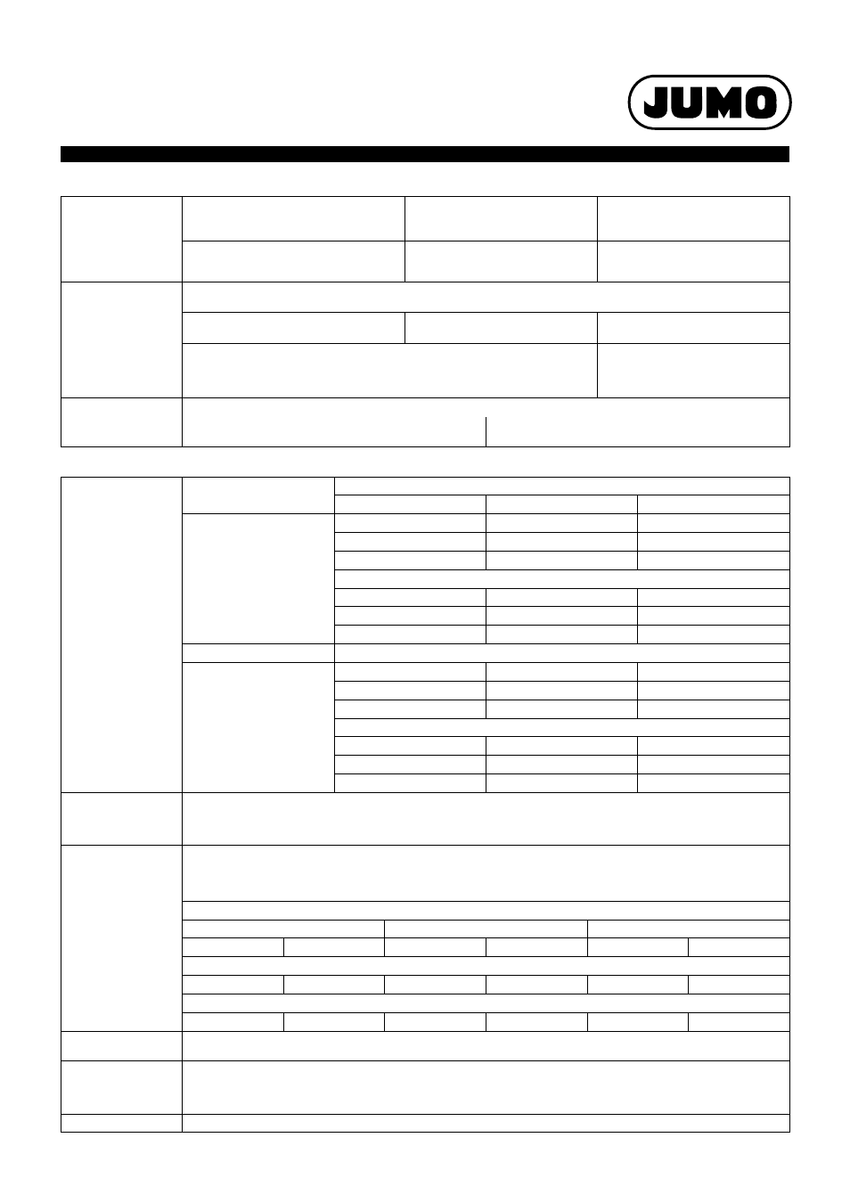
Electrical data
Operating data
Switching element
ATH.-1
ATH.-2
ATH.-20
ATH.-70
ATH.-70/574
Microswitch with changeover contact
Microswitch with N/C contact
and restart lock
Microswitch with N/C contact,
restart lock, and
additional signal contact
Max. switching
capacity
AC 230 V +10 %, 10 (2) A, cos
ϕ = 1 (0.6)
DC 230 V +10 %, 0.25A
With switching differential 1.5 % and 2 %
AC 230 V +10 %, 6 (1.2) A, cos
ϕ = 1 (0.6)
–
–
Gold-plated microswitch, extra code /702*
(* for 3 %, 5 %, and 7 % switching differentials only)
24 V AC / DC, 0.1 A
Contact resistance 2.5 to 10 m
–
Contact reliability
To ensure a high switching reliability, we recommend a minimum load of:
With silver contacts:
AC / DC = 24 V, 100 mA
For gold-plated contacts ("702" symbol):
AC / DC = 10 V, 5 mA
Switching differential
in % of the
control range /
limit value range
Switching function
With liquid-filled measuring system
Nominal value
Possible actual value
TR, TW
3
3 max. 4
Standard
6
6 max. 8
Upon request
1.5
1 max. 2
Extra cost
With gas-filled measuring system
5
4 max. 8
Standard
9
8 max. 12
Upon request
2
1.5 max. 2.5
Extra cost
With liquid-filled measuring system
STW (STB)
5
4 max. 6
Standard
9
8 max. 11
Upon request
2
1 max. 3
Extra cost
With gas-filled measuring system
7
5 max. 12
Standard
9
8 max. 16
Upon request
2
1.5 max. 3
Extra cost
Switching point accu-
racy in % of the con-
trol range / limit value
range
TR, TW: In the upper third of the scale ± 1.5 %, at scale beginning ± 6 %
STB, STW (STB): In the upper third of the scale +0/-5 %, at scale beginning +0/-10 %
Ambient
temperature influence
based on the
control range /
limit value range
When the ambient temperature on the case deviates from the calibration ambient temperature of 22 °C,
a switching point offset occurs.
Higher ambient temperatures = lower switching point
Lower ambient temperature = higher switching point
Surface-mounted thermostats with scale limit value
< 200 °C
÷ 200 °C ≤ 350 °C
> 350 °C ≤ 500 °C
TR / TW
STB/STW (STB)
TR / TW
STB/STW (STB)
TR / TW
STB/STW (STB)
Influence on the switching head
0.08%/K
0.17%/K
0.06%/K
0.13%/K
0.14%/K
0.12%/K
Influence on the capillary per meter
0.047%/K
0.054%/K
0.09%/K
0.11%/K
0.04%/K
0.03%/K
Admissible storage
temperature
-50 to +50 °C
Admissible
ambient
temperature
during use
Max. +80 °C
Rated position (NL)
According to DIN 16 257, NL 0 to NL 90 (different rated positions (NL) upon request)