JUMO 706560 LOGOSCREEN es Data Sheet User Manual
Page 3
2009-12-14/00415638
Data Sheet 70.6560
JUMO GmbH & Co. KG • 36035 Fulda, Germany
Page 3/12
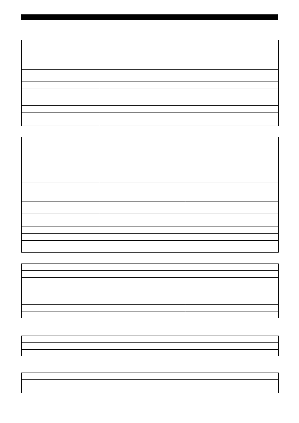
Resistance transmitter and potentiometer
Input for DC voltage or DC current
Transducer short-circuit/break
Binary inputs (extra code)
Outputs
Range
Accuracy
Measuring current
up to 180
Ω
up to 390
Ω
up to 2000
Ω
up to 4000
Ω
±150m
Ω
±300m
Ω
±2
Ω
±4
Ω
500
μ
A
250
μ
A
500
μ
A
250
μ
A
Connection type
resistance transmitter: 3-wire circuit
potentiometer: 2-/3-wire circuit
Shortest span
6
Ω
Probe lead resistance
max. 30
Ω
per core in 4-wire circuit
max. 20
Ω
per core in 2- and 3-wire circuit
up to 200
Ω
range: max. 10
Ω
per core in 2-and 3-wire circuit
Resistance values
freely programmable within the limits in 0.1
Ω
steps
Sampling cycle
6 or 12 channels 125msec
Input filter
2nd order digital filter; filter constant adjustable from 0 — 10.0sec
Basic range
Accuracy
Input resistance
-20
to +70mV
-5
to +105mV
-10
to +210mV
-0.5 to + 12 V
-0.05 to
+ 1.2V
-1.2 to + 1.2V
-12
to +12 V
±80
μ
V
±100
μ
V
±240
μ
V
±6mV
±1mV
±2mV
±12mV
R
IN
≥
1 M
Ω
R
IN
≥
1 M
Ω
R
IN
≥
1 M
Ω
R
IN
≥
470 k
Ω
R
IN
≥
470 k
Ω
R
IN
≥
470 k
Ω
R
IN
≥
470 k
Ω
Shortest span
5mV
Range start/end
freely programmable within the limits
(up to 999mV in 0.01mV steps, above 1V in 1mV steps)
-2 to +22mA
-22 to +22mA
±20
μ
A
±44
μ
A
burden voltage 1V max.
burden voltage 1V max.
Shortest span
0.5mA
Range start/end
freely programmable within the limits in 0.1mA steps
Sampling cycle
6 or 12 channels 125msec
Input filter
2nd order digital filter; filter constant adjustable from 0 — 10.0sec
Features
adjustable linearizations for thermocouples and resistance thermometers
(for connection to transmitters without linearization)
Short-circuit
1
Break
1
Thermocouple
not detected
detected
Resistance thermometer
detected
detected
Resistance transmitter
detected
detected
Potentiometer
not detected
detected
Voltage up to ± 1V
not detected
detected
Voltage above ± 1V
not detected
not detected
Current
not detected
not detected
1
Programmable reaction of instrument, e.g. triggering alarm
Number
7 to DIN VDE 0411, Part 500; 25Hz max., 32V max.
Level
logic “0”: -3 to +5V, logic “1”: 12 to 30V
Sampling cycle
minimum 1 sec
1 relay (ex-factory)
changeover (SPDT), 3A, 230V AC
1
4 relays (extra code)
make /break (SPST-NO/SPST-NC), 3A, 230V AC
1
1 open-collector output (extra code)
25V max., 100mA max.
1
with resistive load. It is not permissible to mix SELV circuits and supply circuits.