JULABO LH 50 Highly Dynamic Temperature Control Systems User Manual
Page 64
Electrical connections
64
1
2
3
4
5
6
REG+E-PROG
Programmer input / temperature recorder output (3.1)
Analog inputs / outputs see page 55
Pin
Signal
1 Voltage output
Channel 1
0 ... 10 V
2 Voltage output
Channel 2
0 ... 10 V
3 GND for outputs
0 V
4 Programmer input
EPROG
0 to 10 V / 0 to 20 mA
5 Current output
Channel 3
0 to 20 mA / 4 to 20 mA
6 GND for Progammer
0 V
1
3
2
ALARM
Alarm output (3.3)
(for external alarm signal)
This potential-free change-over contact is activated in case of an alarm
when pins 2 and 3 are connected.
Switching capacity max. 30 W / 40 VA
Switching voltage
max. 125 V
/
Switching current
max. 1 A
4
1
3
2
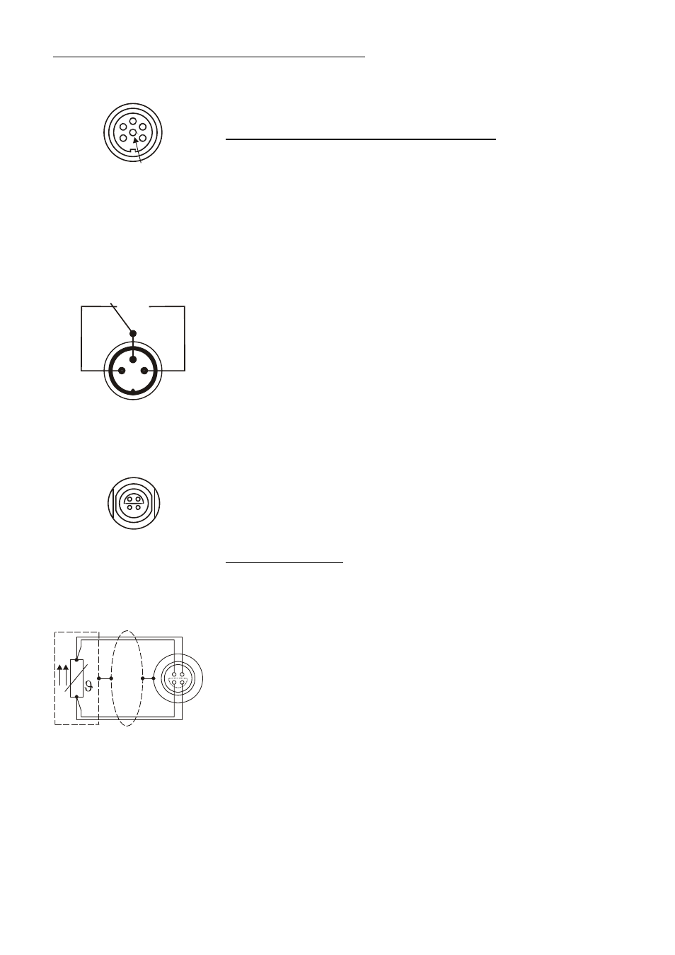
ext. Pt100
1
4
2
3
Shield
Plug
Look on
soldering side.
Pt100
Socket for external Pt100 sensor (3.4)
Pin assignment:
Pin
Signal
1
I+
2
U+
3
U-
4
I-
The shield of the connecting cable is electrically connected to the plug
housing and the sensor tube.