Incra right angle fixture - assembly and use, Step 1. attach faceplate to base, Fig. 8 – INCRA Jig Fence System User Manual
Page 4: Fig. 8a, Fig. 9, Step 2. attach wooden runners, Fig. 10, Fig. 11, Right angle fixture operation
4
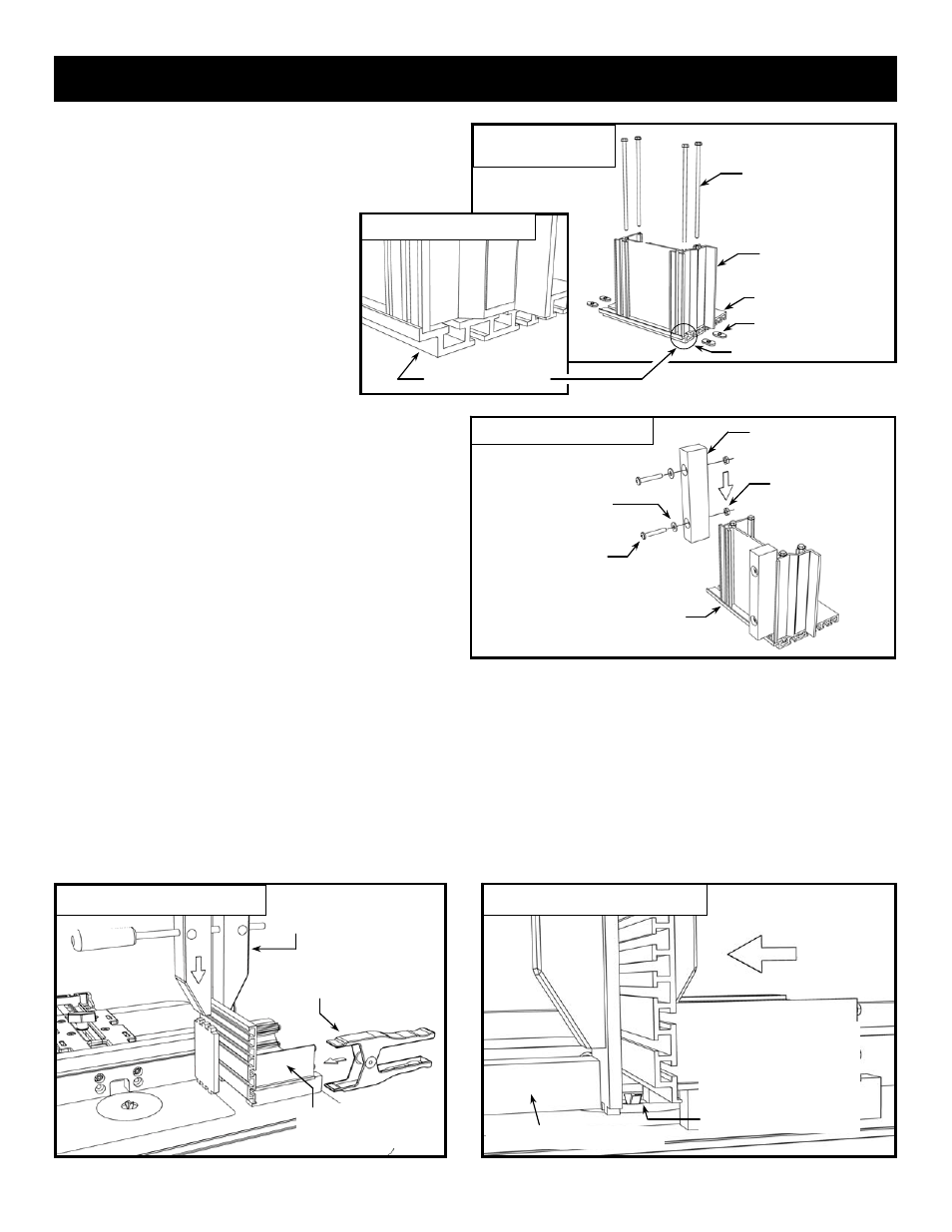
Step 1. Attach faceplate to base.
Attach the INCRA Right Angle Fixture faceplate to the
INCRA Right Angle Fixture base using the (4) supplied
10-32 x 5 1/2” hex bolts and rectangular
nuts. Insert the bolts through the four
holes in the base and loosely attach the
(4) rectangular nuts. Now slide the T-slots
on the back of the faceplate over the
rectangular nuts, Fig. 8. Make sure the
two surfaces marked with an “x” in Fig. 8A
are aligned flush, then securely tighten the
hex bolts.
Fig. 8
Assemble Right Angle Fixture
10-32 x 5 1/2” hex bolts (4)
10-32 rectangular nuts (4)
Right angle fixture faceplate
Right angle fixture base
Fig. 8A
Faceplate alignment
x
x
Align surfaces marked “x”
INCRA Right Angle Fixture - Assembly and Use
10-32 hex nut (4)
Fig. 9
Attach wooden runners
Wooden runner (2)
10-32 x 1 1/4”
Phillips screw (4)
#10 washer (4)
Step 2. Attach wooden runners.
Attach the two wooden runners to the bottom of your
Right Angle Fixture base using the (4) 10-32 x 1 1/4”
Phillips screws, washers and hex nuts as shown in
Fig 9. Each runner should extend about 1/2” beyond
the rear of the base.
Wooden stop block clamped to fence
Fig. 10
Using the Right Angle Fixture
Fig. 11
Avoid contacting wooden runners
Avoid making contact between the
wooden runners and the router bit by
clamping a wooden stop block to the
outfeed side of the fence to stop the
forward travel of the Right Angle
Fixture
Second: Immobilize with spring
clamp (acts like a “third hand”)
Right Angle Fixture operation.
Before clamping a work piece to your Right Angle Fixture,
always press the fixture against your fence, then
immobilize by clamping it to the table with a spring clamp,
Fig. 10. When positioning the work piece against the
faceplate, make sure that the edges of the boards are
against the fence and the ends are contacting the table
surface, then clamp in place using a wooden handscrew
clamp.
CAUTION: Do not allow any part of your
hands to hang below the aluminum body of
the Right Angle Fixture. Always keep hands
well away from the bit.
To avoid contacting the wooden runners with the router bit,
clamp a wooden stop block to the outfeed end of the fence
to stop the forward travel before contact, Fig. 11.
T-slot on bottom of Right
Angle Fixture (4)
See detail in Fig. 8A
First: Push Right Angle
Fixture against the fence
Third: Position stock against fence and
clamp with a wooden jaw clamp