GeoDesy Gigabit AF with auto failover User Manual
Page 19
GeoDesy Kft.
Telefon: 06-1-481-2050
Fax.: 06-1-481-2049
E-mail: [email protected]
http://www.geodesy-fso.com
19
Alignment steps
1. using the crosshair align the units into a roughly aligned position. Please note
that the alignment scope will not be able to provide with a perfect alignment,
this will have to be done using the fine alignment screws referring to the
received level screen on the LCD panel.
2. using the fine adjustment screws on the alignment base set the units to the
highest received level possible. (for further details on how to perform the fine
adjustment refer to 6.2.2 and 6.2.3 chapters)
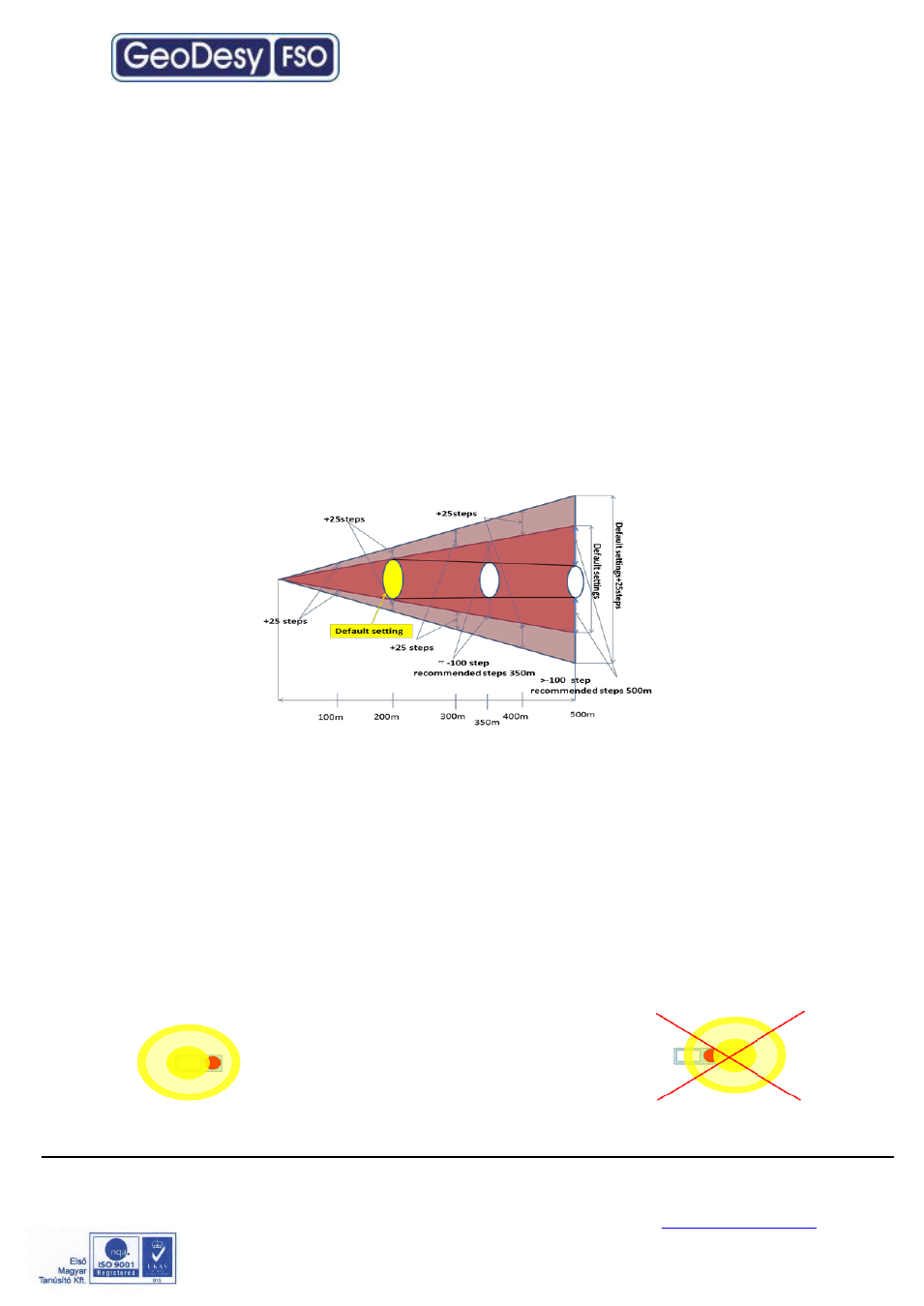
Default distance setting of all
Giga Next AF
laser heads for 200m. As you can see in
below sketch, “+25 STEP” equals ~ 2 cm larger laser beam over 100 meters.
For example, if you would like to install the laser heads over 350 meters than you
will need smaller beam size to reach bigger distance (compared to the default
200m),
so click on “-100 STEP” which will make the laser beam narrower and will
be proper for 350m. While clicking on the “STEP” buttons please check the remote
received level on the laser head.
Please perform the same operation on the other side.
3. After we have got the proper level, please clic
k on “Save position as default”
b
utton. As you have clicked on the “Save position as default” button the laser
heads will enable the AUTO FOCUS mode (enabled). The equipment will
automatically improve the remote level to the most ideal position.
Note: Geodesy FSO shall not be responsible for any failures from improper handling
of the device. If any other screw than the coarse lockers or the fine adjustment is
moved, might decrease the stability of the installation.
Trick for the reliable alignment
Please note that the beam has a powerfull ring on the side of the head and easily can be set to this ring but this is far not as big
as the core part of the beam. So every time you have an
alignment please make sure that when you see the maximum
LED s or a relativly high received level. Keep on moving to
determine where the core part of the beam is. This can be
done easily by looking at the received level you will see that
the received level moves up then it will start move down than
up again. During this time you just had the head moving into
one direction. If you have any doubt on how to do the alignment please contact your distributor
for further help. Or contact GeoDesy FSO technical support.