Alignment of the px0500e1000tp, How to use the alignment base – GeoDesy Gigabit AF with auto failover User Manual
Page 16
GeoDesy Kft.
Telefon: 06-1-481-2050
Fax.: 06-1-481-2049
E-mail: [email protected]
http://www.geodesy-fso.com
16
6.1.1 Alignment of the PX0500E1000TP
The first step after the unit was placed to
the bracket, and the units facing each other.
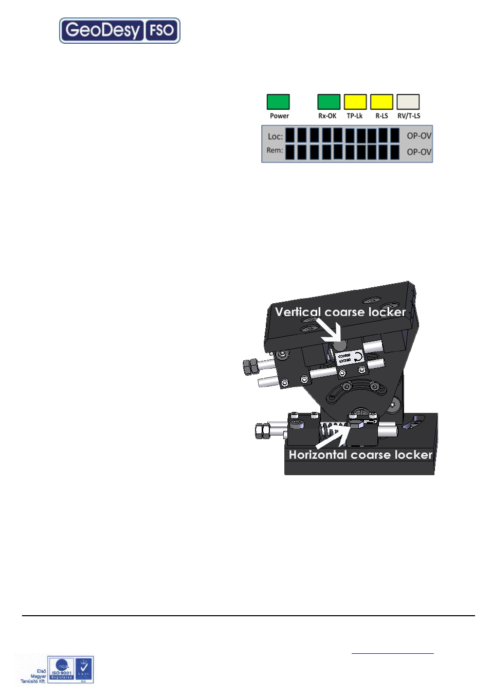
On the back of the receiver you can find the
LEDs and LCD screen for the local received
level and the remote received level.
This help will be very useful because as soon as you have received
– which is very
easy to achieve
– you can see the effect of your local sides movement to the other
side. For further information please check the Meanings of the LCDs chapter.
6.1.2 How to use the alignment
base
1. Loose the Coarse locker on the
horizontal as well as on the
vertical side with a 10mm
spanner
2.
Move the head left - right up
down you should use the built in
telescope to lit up a few LEDs on
the remote end.
3.
When you have lined the unit up
to a rough position lock the
coarse locker with a 10mm
spanner.
4.
Repeat step 1-4 on the remote
end.
5. On the bottom of the unit you can find fine tuning screws one for horizontal
and one for vertical.
6. No tightening is needed on any other screw than the coarse locker.