Warning – Gamber-Johnson 7160-0053 User Manual
Page 3
3/3
WARNING
•The 12" Locking Slide Arm and upper level equipment should not be positioned in the area
where the airbag will be deployed if it is activated. DO NOT position the equipment in front of an
airbag. Equipment positioned in front of an airbag can cause serious injury or death if an airbag
was activated, such as in an accident.
•If installation of the equipment requires that the equipment be placed in front of an airbag,
deactivate the airbag in the vehicle so it cannot be activated in an accident. In order to secure
permission for deactivating the airbag in these circumstances, contact the National Highway
Traffic Safety Administration at 1-800-424-9393 to gain permission to do so. If you have any
questions or need assistance, call Gamber-Johnson at 1-800-456-6868.
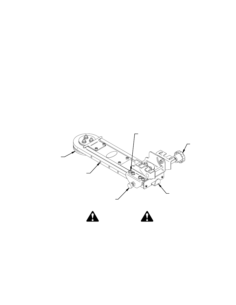
How to use the Fire Arm:
The 12" Locking Slide Arm is designed to accomodate four motions of adjustment.
The first being a 360 degree swivel that is actuated by the front lever. Pulling out on
the lever releases the gear latch located in the base and allows the mount to swivel.
To latch the arm in place, position the arm in the desired location and release the
spring loaded lever. Wiggle the arm back and forth to make sure the lever has
engaged the teeth on the gear.
The second motion is the 12" slide. To actuate the slide, pull out and hold the
spring loaded pin. Push or pull the mount along the slide to the desired location and
release the pin. Push or pull the mount until the pin latches into position. There are 6
mounting positions along the slide. The spring pin can be moved to the opposite side
if required. To move the pin remove the (8) M6 cap screws that attach the slide plate
to the slide. Rotate the clevis and slide plate assembly 180 degrees and reinstall the
M6 cap screws to hold the clevis in place.
The third motion is the clevis swivel. The clevis can swivel 360 degrees around the
3/8" diameter bolt that attaches the clevis to the slide plate.
The fourth motion is the clevis tilt. The clevis can tilt from 0 to 90 degrees by
loosening the handle on the right side of the clevis adjusting the tilt to the desired
angle and retightening the handle.
Front Lever
Clevis Handle
Spring Loaded Pin
Slide Adjustment
Base
M6 Cap Screws