Flint & Walling CCF Series Air Induction Water Treatment Systems User Manual
Page 7
7
remier
remier
roducts
roducts
P
P
P
P
WATER TREATMENT
®
Addendum for CCF Series
Automatic Water Filters Only
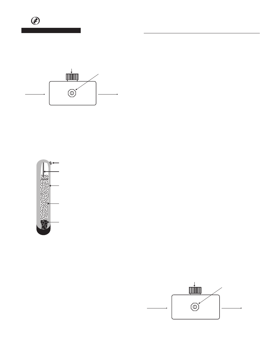
and pressure control switch is located on pressure
tank side of the air induction assembly (See Figure
2). Allow 8” of straight pipe on both sides of air
induction assembly.
WATER FLOW
WATER FLOW
FLOW ADJUSTING SCREW
SUCTION
PORT
IL1041
Figure 2 - Air Induction Assembly
INSTALLINg THE FILTER
1. Media was shipped separately. Carefully unscrew
the control valve. Be sure to “plug” the top of the
distributor tube using tape or some other means. Do
not allow filter media to enter inside of distributor
tube (See Figure 3).
Distributor Tube
Media Tank
Filter Media
Gravel - preinstalled
Dome Hole (”D” suffix models only)
Figure 3 - Media Tank Cutaway
2. Pour the separately shipped media into media tank.
3. Replace control valve on media tank. Lubricate
o-rings on control valve with silicone lubricant. DO
NOT USE PETROLEUM JELLY.
4. Lubricate bypass valve o-rings with silicone lubricant
and secure to the control valve using adapter
couplings, clips and screws.
5. Cut main supply line as required to fit plumbing to
the inlet and outlet of bypass valve. Make certain
water flow enters through the Inlet and discharges
through the Outlet of bypass valve.
6. Attach drain line to drain line fitting. Position drain
line over drain and secure firmly. To prevent back
siphoning, be sure to have adequate air gap of at
least 2 inches.
7. Make certain bypass valve is in the “bypass” position.
Turn on power to well pump or open main supply
valve completely.
8. Plug control valve into a non-switched 115V power
source.
9. Manually stage filter to the backwash position (see
service manual).
10. Open inlet valve and allow the unit to fill SLOWLY.
This will allow air to escape from the media tank.
Once water continually flows to drain, open both
inlet and outlet valves fully.
11. Check for leaks and allow filter to backwash for at
least 10 minutes, or until water flowing from drain
runs clear.
12. Allow unit to fully regenerate (see service manual).
13. Models CCF10D and CCF20D have a dome hole/plug
located in the upper dome of the mineral tank. This
is used to replenish mineral as required. DO NOT
remove dome hole plug without first depressurizing
the tank.
ADJUSTINg THE AIR INDUCTION ASSEMBLy
1. Open nearest faucet until pump starts, then close
faucet.
2. Place finger lightly over SUCTION PORT (See figure 2).
A slight suction should be detected for approximately
ONE-THIRD of pumping cycle. (Do not confuse with
one-third of PRESSURE RANGE).
3. If suction duration is too short, increase by turning
FLOW ADJUSTING SCREW CLOCKWISE. To decrease
duration, turn COUNTER CLOCKWISE.
4. Repeat steps 1 through 3 until proper setting is
obtained.
NOTE: When the duration of the suction is too long, cold
water may have a “milky” appearance caused by excess
air in the system. Correct this condition by reducing the
duration of suction. This condition is commonly associated
with bladder type pressure tanks In extreme cases where
elimination of excess air prevents system from performing
satisfactorily, it may be necessary to install a standard air-
to-water type pressure tank with an air relief valve.
WATER FLOW
WATER FLOW
FLOW ADJUSTING SCREW
SUCTION
PORT
IL1041
Figure 2