Before installing your filter, Installation, Remier – Flint & Walling CCF Series Air Induction Water Treatment Systems User Manual
Page 6: Inspection and handling your filter, Conduct a thorough water test, Water analysis, Locating equipment correctly, Facts to remember while planning your installation, Check water pressure, Check pumping rate of well pump
6
remier
remier
roducts
roducts
P
P
P
P
WATER TREATMENT
®
Addendum for CCF Series
Automatic Water Filters Only
BEFORE INSTALLINg yOUR FILTER
INSPECTION AND HANDLINg yOUR FILTER
Be sure to inspect the equipment for shipping damage
and notify the transportation company if damage exists.
Handle the filter with care, as damage can result if
dropped or if the filter is set on a sharp object.
CONDUCT A THOROUgH WATER TEST
Your water should have a thorough analysis prior to the
selection of water conditioning equipment. Enter your
analysis below:
WATER ANALySIS
IRON (fe)
__________ ppm
Manganese (Mn)
__________ ppm
pH
__________
Tannins
__________ ppm
Hydrogen Sulfide (H2S)
__________ ppm
NOTE: Hydrogen Sulfide must be tested at the well site.
Failure to conduct an “on site” analysis will result in
inaccurate test results.
LOCATINg EQUIPMENT CORRECTLy
The location of your filter should be selected carefully. A
variety of conditions will contribute to proper location as
follows:
1. Locate as close as possible to the source of water
supply.
2. Locate as close as possible to drain, i.e. laundry tub or
floor drain.
3. Locate in correct relationship to other water
treatment equipment (See Figure 1).
4. Allow sufficient area around the equipment for
service.
FACTS TO REMEMBER WHILE
PLANNINg yOUR INSTALLATION
1. All installation procedures MUST conform
to local and state plumbing codes.
2. All water MUST pass through the air
induction assembly, pressure tank and
the Chemical-Free Iron Filter (See Figure
1)
3. If lawn sprinkling, a swimming pool or
geothermal heating/cooling are to be
treated by the Chemical Free filter, a
larger model filter MUST be selected
to accommodate the higher flow rate
demands.
4. IMPORTANT: Always use Teflon tape on threaded
plastic fittings. NEVER use pipe dope, as it will
deteriorate the plastic fittings.
CHECK WATER PRESSURE
Minimum water pressure required at the inlet of the
filter is 30 psi. IF PRESSURE IS OVER 125 PSI, A PRESSURE
REGULATING VALVE MUST E INSTALLED TO REDUCE
WATER PRESSURE.
NOTE: Pressure regulating valve must be installed in
water line ahead of the air induction assembly.
CHECK PUMPINg RATE OF WELL PUMP
The pumping rate of your well pump must be sufficient
to properly backwash the filter. Check backwash flow rate
required for specific filter model.
Water Pressure
Low
_____ PSI
High
_____
PSI
Pumping Rate
_________ GPM
INSTALLATION
INSTALLINg THE AIR INDUCTION ASSEMBLy
1. Shut off all water at the main supply. On a private
well system, turn off power to the pump and drain
pressure tank. Make sure pressure is relieved from
complete system by opening nearest faucet to drain
system. SHUT OFF FUEL SUPPLY TO WATER HEATER.
2. Cut main supply line as required to fit air induction
assembly in plumbing between well pump and
pressure tank. Air induction assembly may be installed
in a vertical or horizontal position. Position air
induction assembly so that the flow adjusting screw
is accessible for adjustment by screwdriver. Install
unions to facilitate air induction assembly removal
and inspection. Be certain the Flow Arrow on air
induction assembly points toward the pressure tank
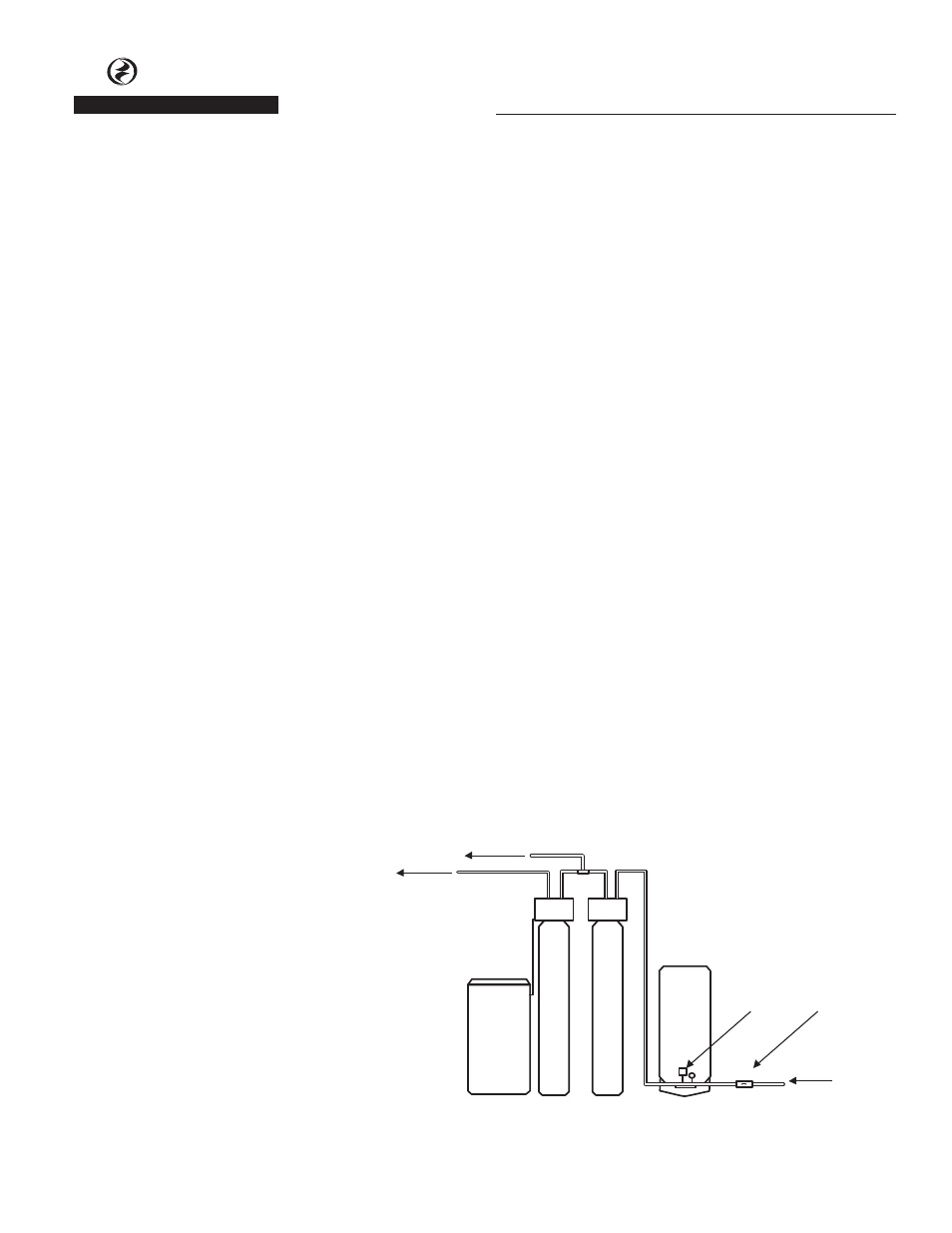
Figure 1 - Standard Installation
IRON FREE WATER
IRON FREE
SOFT WATER
WATER
SOFTENER
WATER
FILTER
PRESSURE
TANK
PRESSURE
SWITCH
AIR INDUCTION
ASSEMBLY
WELL WATER
FROM PUMP
IL1040