Flint & Walling FJ Shallow Well User Manual
Page 4
© Copyright 2006. All rights reserved.
4
This pump has not been evaluated for use in
swimming pool areas.
Assembly (Continued)
To reduce the risk of electric shock, install with
motor and all electrical components above
the top grade level of sump. This pump is not
submersible.
Use wire size specified in wiring Chart C. If
possible connect pump to a separate branch
circuit with no other appliances on it. If motor
wiring diagram differs from diagram shown
below, follow diagram on motor.
Wire motor for correct
voltage. See “Electrical”
section and Motor Data
Charts A & C of this
manual, and motor
nameplate.
Ground motor before
connecting to electrical
power supply
Meet national electrical
code and local codes for
all wiring.
Do not handle a pump or pump motor with wet
hands, or when standing on a wet or damp
surface or in water.
Follow wiring instructions in this manual when
connecting to power lines.
IMPORTANT: Do not use an extension cord
or splice wires. Joints should be made in an
approved junction box. If the above information
or the following wiring diagrams are confusing,
consult a licensed electrician.
Always disconnect power
source before performing any work on or near the
motor or its connected load.
Never run pump dry or against
a closed discharge. To do so can or may cause pump
to overheat, damaging seal and possibly causing
burns to persons handling pump. Fill pump with
water before starting.
Wiring the Pressure Switch
1. Remove pressure switch cover to expose wiring
terminals.
2. Insert motor wires through side hole of pressure
switch and attach to the two inside terminals
marked “motor” (See Figure 3.)
3. Connect the green ground wire of the motor and
the power supply to the switch ground terminals.
4. Connect the power supply wire to the two
pressure switch terminals marked “line” and
replace the switch cover.
M
LINE 2
LINE 1
POWER SUPPLY
LINE
LINE
MO
TO
R
MO
TO
R
GREEN
GROUND
WIRE
GREEN
GROUND
WIRE
IL0626
Figure 3
Make certain that the power
supply conforms to the electrical specifications of the
motor supplied. See Motor Data Chart A.
Specific Wiring Procedure 115V or 230V
1. The motors are prewired from factory for use
with 115V service. Motors are dual voltage
(115/230V), and may be field connected for
230V service.
2. To change voltage, remove the junction box
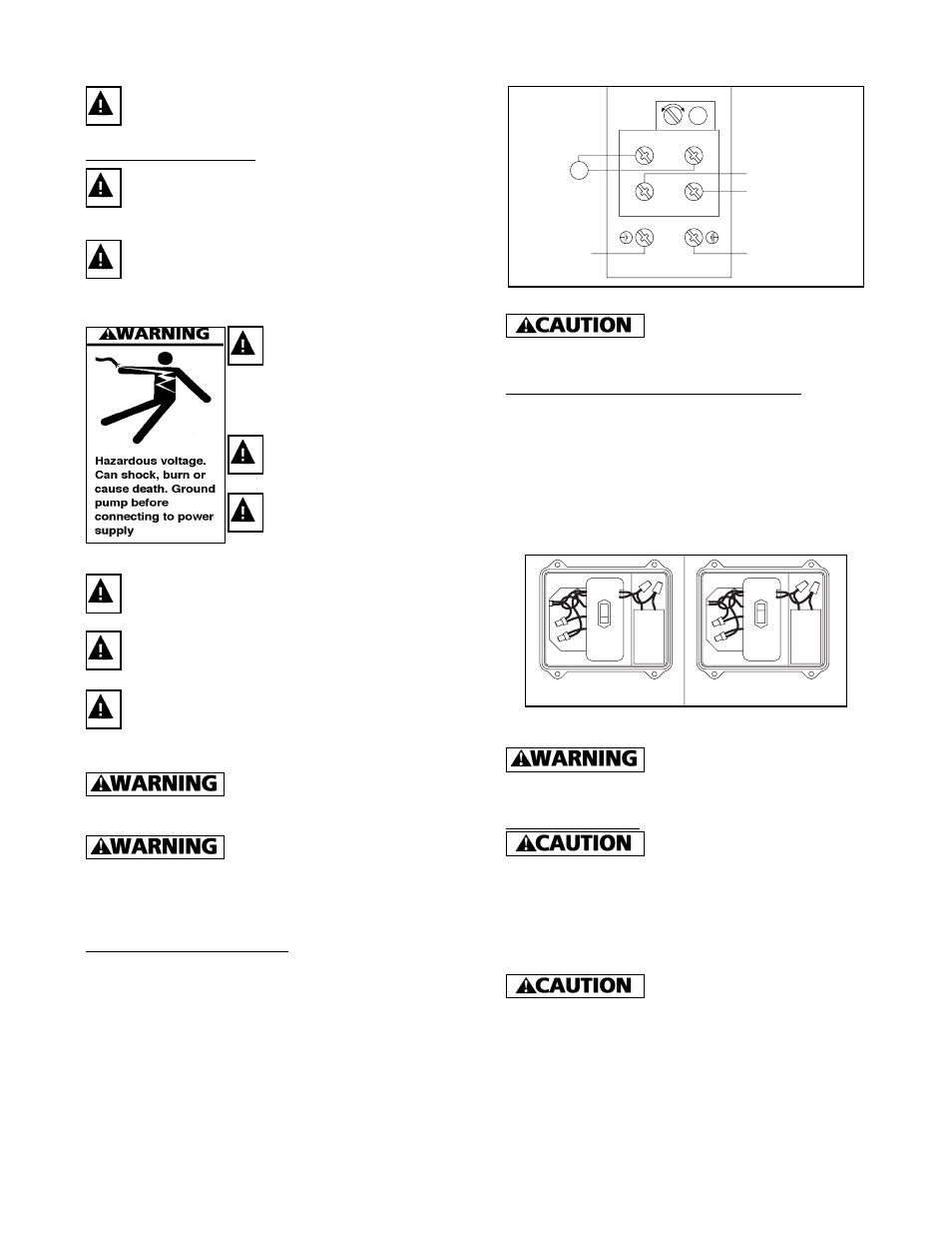
access cover (See Figure 1).
3. Move the switch to 230V position. (See Figure
4).
115
230
IL0165
Figure 4
Replace access cover before
starting or operating pump. Failure to do so can
result in personal injury.
Priming the Pump
Do not touch an operating
motor or engine. They are designed to operate at high
temperatures.
IMPORTANT: Pump must be primed. Make sure
pump is full of water before running. Failure to do
so will cause damage to the pump and void the
warranty.
This pump has been evaluated
for use with water only.