Flint & Walling FJ Shallow Well User Manual
Page 2
© Copyright 2006. All rights reserved.
2
General Safety Information
Carefully read and follow all safety instructions
in this manual and on pump. Keep safety labels
in good condition. Replace missing or damaged
safety labels.
This is a SAFETY ALERT SYMBOL. When you
see this symbol on the pump or in the manual,
look for one of the following signal words and
be alert to the potential for personal injury or
property damage.
Warns of hazards that will cause
serious personal injury, death or major property
damage if ignored.
Warns of hazards that can cause
serious personal injury or death, if ignored.
Warns of hazards that can cause
minor personal injury, product or property damage if
ignored.
Indicates factors
concerned with operation, installation, assembly or
maintenance which could result in damage to the
machine or equipment if ignored.
NOTE: Indicates special instructions which are
important but are not related to hazards.
Do not use to pump flammable or explosive
fluids such as gasoline, fuel oil, kerosene,
etc. Do not use in flammable and/or
explosive atmospheres.
Hazardous pressure! Install pressure
relief valve in discharge pipe. Release all
pressure on system before working on any
component.
This product contains chemicals
known to the State of California to cause cancer and
birth defects or other reproductive harm.
NOTE: Pumps with the cCSAus mark are tested to
UL Standard UL778 and certified to CSA Standard
C22.2 No. 108.
1. Wear safety glasses when working with pumps.
2. Pump water only with this pump.
3. Periodically inspect pump and system
components.
4. Protect electrical cord. Replace or repair
damaged or worn cords immediately.
5. Do not insert finger or any object into pump or
motor openings.
6. Do not allow pump or any other system
component to freeze. Freezing may damage
system, leading to injury or flooding. Allowing
pump or system components to freeze will void
the warranty.
7. An acceptable motor switch shall be provided at
the tme of installation.
Never examine, make wiring
changes or touch the motor before disconnecting the
main electrical supply switch.
Unpacking
1. Open carton and remove package that has been
packed with the pump. This package contains
the pressure switch.
2. Remove pump from carton.
3. Check for loose, missing or damaged parts.
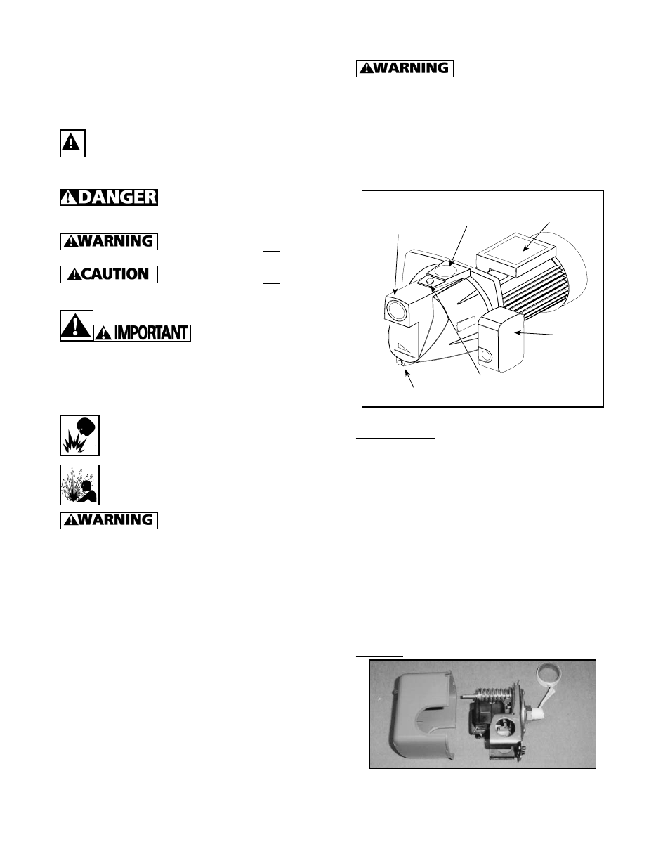
IL0607
1” NPT
Discharge
Port
1-1/4” NPT
Suction Port
Pressure
Switch
1/2” Priming
Port
Drain Plug
Junction Box
Figure 1
Pre-Installation
For installation the following general materials may
be required:
• PVC cement (if plastic pipe is used)
• Teflon tape
• Pipe, pipe couplings and fittings
• 1” nipple (for discharge)
• 1” tee or 90° elbow (for discharge)
* 1” pipe plug if tee is used
• 1-1/4” foot valve (for cased wells)
• 1-1/4” check valve (for driven wells)
• Single pipe well seal for 1-1/4” pipe (cased or
dug wells)
• Copper electrical wire (See Wiring in Electrical)
• Romex strain relief for pressure switch
Assembly
1. Apply two (2) wraps of Teflon tape to threads of
the pressure switch screw. Refer to Electrical
section for pressure switch wiring.