Flint & Walling FJ Shallow Well User Manual
Page 3
© Copyright 2006. All rights reserved.
3
Assembly (Continued)
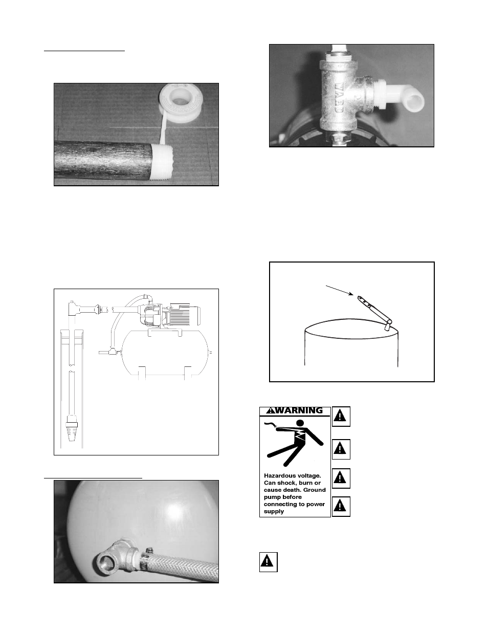
2. Screw in pressure switch to 1/4” tapping on side
of pump hand tight. Tighten pressure switch with
wrench.
3. Use Teflon tape or pipe joint compound for
making all threaded connections to the pump.
4. Assemble 3/4” pipe to discharge port of pump.
Assemble suction pipe with union to front
of pump. Unions installed near pump and
well will aid in servicing. Leave room to use
wrenches.Tighten joints to approximately 140 ft.
lbs.
5. Bolt pump to solid, level foundation. Support all
piping connected to the pump.
IL0155
Figure 2
Pressure Tank Installation
1. Assemble tank Tee to end of tank. Screw flexible
hose to tank Tee.
2. Screw elbow fitting to discharge tee. Push flexible
hose onto elbow. Tighten clamp with screwdriver.
3. Connect service line to tank Tee.
4. NOTE: DO NOT install a check valve between
pump and pressure tank. This will cause the
pressure switch to malfunction.
IMPORTANT: Your pump pressure switch is set for
a 20-40 PSI (1.4 - 2.8 Kg/cm2) range and requires
a tank pre-charge of 18 PSI for proper operation
(See Figure 7.)
IL0167
Checking Tank Pre-Charge
Check pressure
with tire gauge
Pre-Charged Pressure
Tank
Figure 3
Ground motor before
connecting to electrical
power supply
Failure to ground motor
can cause severe or fatal
electrical shock hazard
Do not ground to a gas
supply line.
To avoid dangerous or fatal
electrical shock, turn off
power to motor before
working on electrical
connections.
Supply voltage must be within ±10% of
nameplate voltage. Incorrect voltage can
cause fire or seriously damage motor and
voids warranty. If in doubt, consult a licensed
electrician.
3