Installation – Flint & Walling Pressure Booster Pumps Instructions User Manual
Page 5
5
Copyright © 2014 FLINT & WALLING, INC. • 95 North Oak St. • Kendallville, IN 46755
flintandwalling.com
IL1014
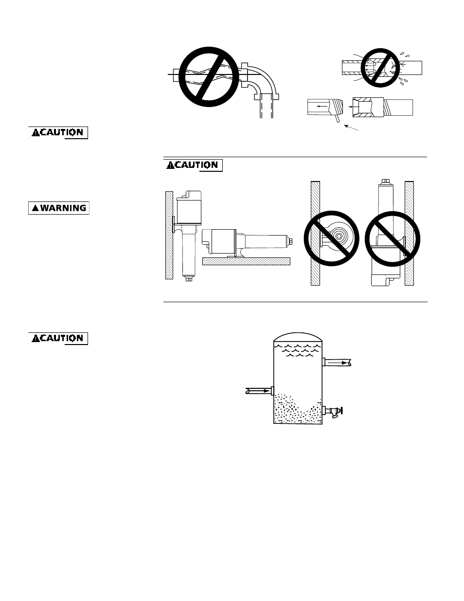
Mount pump in correct position or pump failure will result.
Figure 2 - No Air Pockets in Inlet Pipe
Figure 3 - Inlet Pipe Must Not Leak
Figure 5
IMPORTANT: Clean all filters and strainers on a regular schedule.
IL0418
IL0419
IL0420
No Sags
Sags Allow Air Pockets
No Air Leaks In
Inlet Pipe
Pipe Joint Compound
Will Damage Plastic
If Air Flows
Water
Won’t
If Air Pockets Form,
Water Won’t Flow
Use Teflon Tape
IL1013
Correct
Incorrect
Figure 4A
Figure 4B
IL0421
SAND AND SEDIMENT TRAP FILTER
Outlet
Clean Out
Standard Pressure
Tank - 42 Gallon Or
Larger
Inlet
Sand Settles To The Bottom
IMPORTANT: The entire system must
be air and water tight for efficient/
proper operation.
Installation
PUMP INSTALLATION
IMPORTANT: Pump is built to handle
clear water only; it is not designed to
handle water containing sand, silt or
other abrasives.
1. Refer to Figures 6, 7, and 8 for
typical installations.
Support pump and
piping when assembling and when
installed. Failure to do so may cause
piping to break, pump to fail, motor
bearing failures, etc.
2. If the pump is used as part of a
permanent installation, bolt to a
rigid foundation.
!
Use only
components that
are rated for
maximum pressure pump can produce
when used in boosting system or any
other system. Do not exceed the total
maximum pressure boost as listed per
model in Performance Charts B.
PRESSURE BOOST SYSTEMS
1. On pressure boost systems, locate
the pump so that there will always
be a positive supply of water to
the pump (See Figures 6, 7 and 8).
2. For service convenience, install a
gate valve and union in the inlet
and discharge line.
Do not use a globe
valve or other
restricting type of
valve that will seriously restrict the
pumps discharge capacity.
3. Install a check valve as shown in
Figure 6. Be sure check valve flow
arrows point in the direction of
water flow.
4. Whenever dirt, sand or debris is
present in the supply water, install
a strainer or filter on the inlet side
of the pump (See Figure 7).
NOTE: For heavy amounts of
sediment, install a trap filter on the
inlet side of the pump (See Figure 5).
NOTE: Pressure gauges installed
before and after the filter will show
pressure differential indicating
the need for filter replacement or
cleaning.