Flint & Walling Pressure Booster Pumps Instructions User Manual
Page 10
10
Copyright © 2014 FLINT & WALLING, INC. • 95 North Oak St. • Kendallville, IN 46755
flintandwalling.com
Operation (Continued)
START - UP PROCEDURE
Once the preceding instructions have been completed, the
pump can be started.
1. During the first few hours of operation, inspect the
pump, piping and any auxiliary equipment used in
connection with the unit.
2. Check for leaks, excessive vibration or unusual noises.
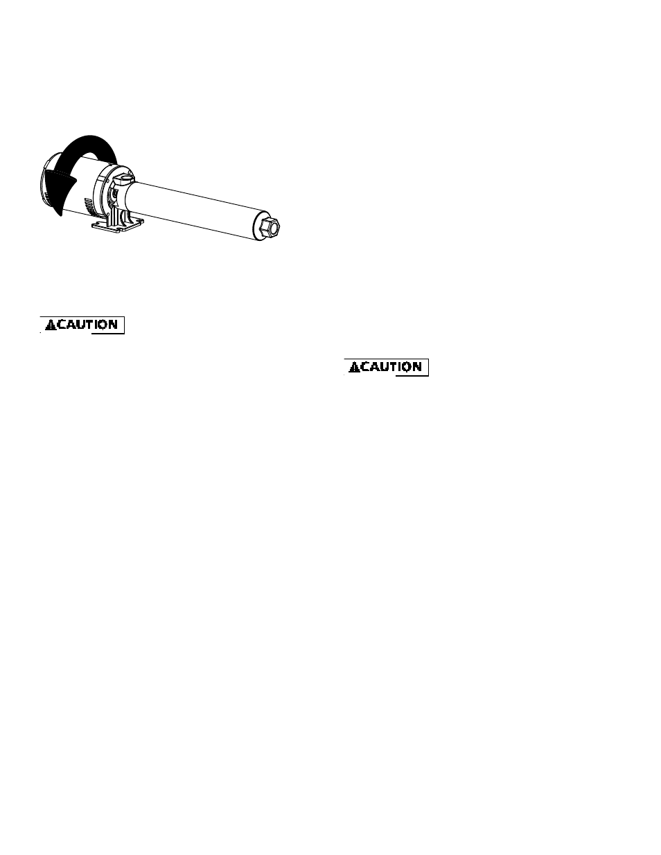
Figure 15 - Correct Motor/Pump Rotation (all units)
NOTE: See rotation arrow on inlet casting.
IL1825
Maintenance
Disconnect power supply and
depressurize system before servicing
pump or removing any component.
ROUTINE
Pump should be checked routinely for proper operation.
Replace or clean all filters and line strainers on a regular
basis.
DRAINING
This pump cannot be completely drained because of internal
design. Most of the liquid can be drained by tilting the
discharge forward after removing discharge casting; or, the
liquid can be drained through the inlet port. Store in heated
areas.
CLEANING
If used for spraying insecticides, pump should be thoroughly
flushed with clean water after using.
LUBRICATION
The motor has prelubricated bearings. No lubrication is
required.
SERVICING THREE-PHASE UNITS
Loctite (thread sealer) is used on the threads between
the motor shaft and the pump shaft coupling. When
reassembling, reapply thread sealer.
PUMP DISASSEMBLY
To disassemble the pump, refer to the exploded parts view
and Figures 16, 17 & 18
Tools Required:
•
Block of wood (2” x 4” x 12”)
Piece of 3/4” pipe (12” to 24” long)
•
Pipe wrench
•
Strap wrench
•
1/4” Dowel rod (about 24” long)
•
9/16” Open end wrench
•
3/8” Open end wrench
1. To stabilize pump during disassembly, place block of
wood underneath pump barrel.
2. Thread pipe into pump inlet port. This acts as a handle.
3. Using the pipe wrench, remove the discharge head,
turning CCW (counter clockwise).
4. With the strap wrench, loosen the barrel, turning CCW
(counter clockwise). DO NOT use pipe wrench on pump
barrel.
5. Holding the impeller stack in place, position pump in
upright position, standing unit on the motor end cover.
6. Use the 1/4” dowel rod to hold the stages down and in
place on the pump shaft. Remove pump barrel.
7. Slide the stages off the pump shaft onto the 1/4” dowel
rod. Leave stages on rod and carefully set aside.
NOTE: There may be some small .010” shim washers located
next to the pump shaft coupling. Keep these shims for
re-assembly.
8. Through the side opening of the mounting frame, hold
the motor shaft with 9/16” wrench. Remove the shaft
and coupling from the motor using the 3/8” wrench on
the hex shaped pump shaft.
NOTE: If the hex shaft comes free, leaving the coupling
attached to the motor, use vise grips to free the coupling.
MECHANICAL SEAL REPLACEMENT
1. Follow instructions under “Pump Disassembly”.
2. Remove the mechanical seal assembly.
a. The rotary portion of the seal assembly (carbon ring,
Buna-N gasket and spring will slide easily off the end of
shaft).
b. Using two (2) screwdrivers, pry the ceramic seal and rub-
ber gasket from the recess of the mounting ring (See
Figure 16).
The precision lapped faces of the
mechanical seal are easily damaged.
Handle the replacement seal carefully.
Short seal life will result if seal faces (ceramic & carbon) are
nicked, scratched or dirty.
3. Clean the seal cavity of the mounting ring and the
motor thoroughly.
4. Wet outer edge of rubber cup on ceramic seat with
liquid soap solution. Use sparingly (one drop only).
NOTE: Liquid soap solution - one drop of liquid soap
combined with one teaspoonful of water.
5. With thumb pressure, press ceramic seal half firmly and
squarely into seal cavity. Polished face of ceramic seat
is up. If seal will not seat correctly, remove, placing seal
face up on bench. Reclean cavity. Seal should now seat
correctly (See Figure 17).
6. If seal does not seat correctly after recleaning cavity,
place a cardboard washer over polished seal face and
carefully press into place using a piece of standard clean
3/4” pipe as a press (See Figure 18).