Maintenance (continued) – Flint & Walling Pressure Booster Pumps Instructions User Manual
Page 11
11
Copyright © 2014 FLINT & WALLING, INC. • 95 North Oak St. • Kendallville, IN 46755
flintandwalling.com
Maintenance (Continued)
IMPORTANT: Do not scratch seal face.
7. Dispose of cardboard washer and recheck seal face to
be sure it is free of dirt, foreign particles, scratches and
grease.
8. Inspect shaft to be sure it is free of nicks and scratches.
9. Apply liquid soap solution sparingly (one drop is
sufficient) to inside diameter of rubber rotating member.
10. Slide rotating seal member (carbon face down toward
ceramic face) and spring over the shaft.
IMPORTANT: Do not nick or scratch carbon face of seal
when handling.
MOTOR REPLACEMENT
The motor can be replaced with any standard Nema 56J jet
pump motor (of proper HP for each pump) by referring to
the following instructions.
1. Follow steps as outlined under Rotary Seal Replacement
and Pump Disassembly.
2. Remove cap screws that connect the motor to the
mounting ring and pull motor away.
3. Replace motor with standard Nema 56J jet pump motor
by positioning motor against the mounting frame and
assembling with four (4) cap screws.
IMPORTANT: Because damage to the shaft seal can occur in
disassembly, a new seal will be necessary.
PUMP REASSEMBLY
Before reassembling the pump, carefully inspect the
component parts of the cartridge (stage) assembly, looking
for damage, wear or heat distortion. Pay careful attention
to spacing direction of components, and location of shims.
Refer to Figure 19 for proper facing and parts arrangement.
If damage to Stage components is evident, a complete
cartridge assembly or individual stage assemblies are
available for replacement (See Replacement Parts List).
1. Reassembly should follow the reverse order of the
disassembly procedure with special care given to
replacement of the rotary seal.
2. Check top and bottom of o-rings for damage. It is recom-
mended that new o-rings be used.
3. Do not use pipe compound of Teflon tape on barrel
threads. The o-rings will prevent pump from leaking.
4. After pump is reassembled, tighten the discharge head to
a torque of 45-50 ft/lbs. If torque wrench is not available,
tighten firmly but avoid distortion or damage to plastic
internal parts.
5. After reassembly, apply power momentarily to unit (15 to
30 seconds). The pump and motor should rotate freely or
with a light rubbing.
IL0554
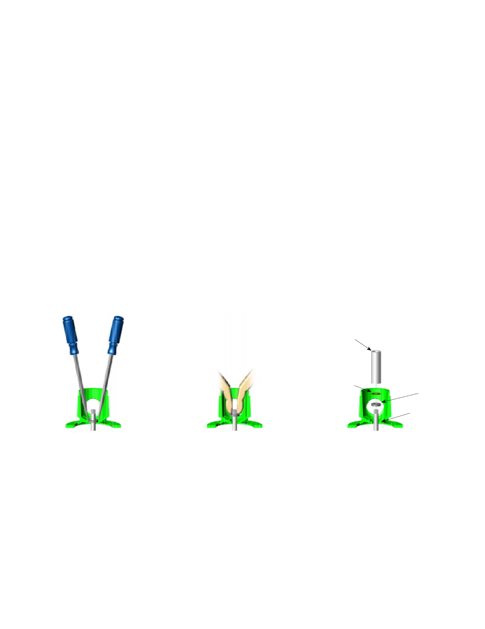
Figure 16 - Remove Mechanical Seal
Figure 17 - Press In Seal
Figure 18 - If Necessary, Press With
Cardboard And Pipe
3/4” Pipe
Press Carefully
Seal
Seal Cavity
Cardboard
Washer
Protects Seal
Face