Booster pump parts drawing, Internal parts detail – Flint & Walling Pressure Booster Pumps Instructions User Manual
Page 13
13
Copyright © 2014 FLINT & WALLING, INC. • 95 North Oak St. • Kendallville, IN 46755
flintandwalling.com
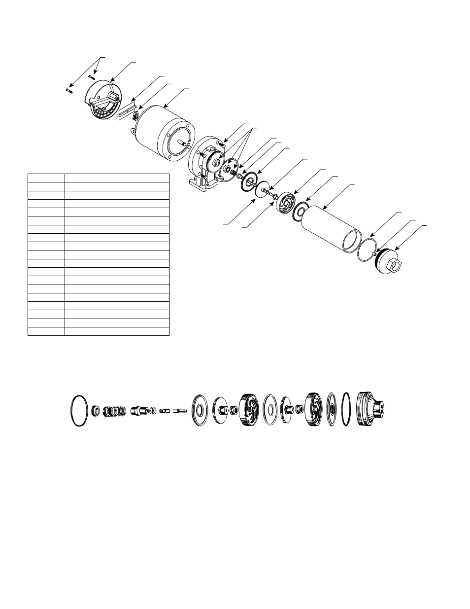
Booster Pump Parts Drawing
Figure 20 - Cartridge Assembly Includes Discharge Bearing, Shaft & Coupling Assembly, Diffuser Plate, Impellers, Diffuser
Bearings, Diffusers and O-rings
NOTE: Illustration shows only two stages. Pump has multiple stages. Individual parts are not available separately.
IL0308
Internal Parts Detail
IL0127
4
10A
10
1B
1A
1
9
8
2
5
7
6A
6E
6D
6A
5
4A
3
6C
6B
4
ITEM NO. DESCRIPTION
1
Motor
1A
†Governor
1B
†Switch Motor
2
Seal, Rotary
3
Barrel
4
Discharge Head
4A
Discharge Bearing
5
O-ring (2)
6A
Plate, Diffuser
6B
Impeller
6C
Diffuser
6D
Diffuser Bearing
6E
Shim as Required
7
Shaft and Coupling Assembly
8
Mounting Ring
9
Hex Head Bolts (4)
10
†MotorAccess Cover
10A
†Screws, Access Cover (2)
*See note below parts included in cartridge assembly.
†ODP Motor Only
Figure 19