Flint & Walling Commander Pro 75 User Manual
Page 4
4
95 North Oak Street • Kendallville, IN 46755
Copyright 2012. All Rights Reserved.
and ultimate motor failure. Oversized cable is costly and
not necessary. Refer to cable selection chart for proper
cable selection. Cable is selected for the maximum
pump setting plus the offset distance to the service
entrance.
13. Ground Wire — The National Electric Code (NEC 250-
43) requires a separate ground wire be run down the
well to the submersible pump and to be connected to
all exposed metal parts of the pump and motor. Refer
to the most recent National Electric Code (NEC) for
additional grounding information. All wiring should be
done by a competent electrician.
INSTALLATION
SUBMERSIBLE CABLE INSTALLATION
1. Check power source. Check electrical supply for
correct fusing, correct wire size, and adequate
grounding and transformer size.
Since most submersible pump problems
are electrical, it is very important that all electrical work
be done properly. Therefore, all electrical hook-up work
or electrical service work should be done by a qualified
electrician or serviceman only!
2. Follow wiring directions in installation and operations
manual.
3. Check cable size against the Submersible Wire Size
Chart. Use extreme care; this is a very important
step. If required length falls between two wire sizes,
use the larger of the two wire sizes (smaller number).
IMPORTANT: Use of wire sizes smaller than those
specified in the charts will cause low starting voltage,
may cause early pump failure and will void the warranty.
Larger wire sizes may always be used for better operating
economy.
Maximum wire lengths connecting the motor to the controller
Subdrive
Copper Wire size
(AWG)
14
12
10
8
6
Subdrive 75 Maximum Length (Ft.) 420 670 1060 1670
-
Subdrive 100 Maximum Length (Ft.) 320 510 810 1280 2010
Subdrive 150 Maximum Length (Ft.) 240 390 620 990 1540
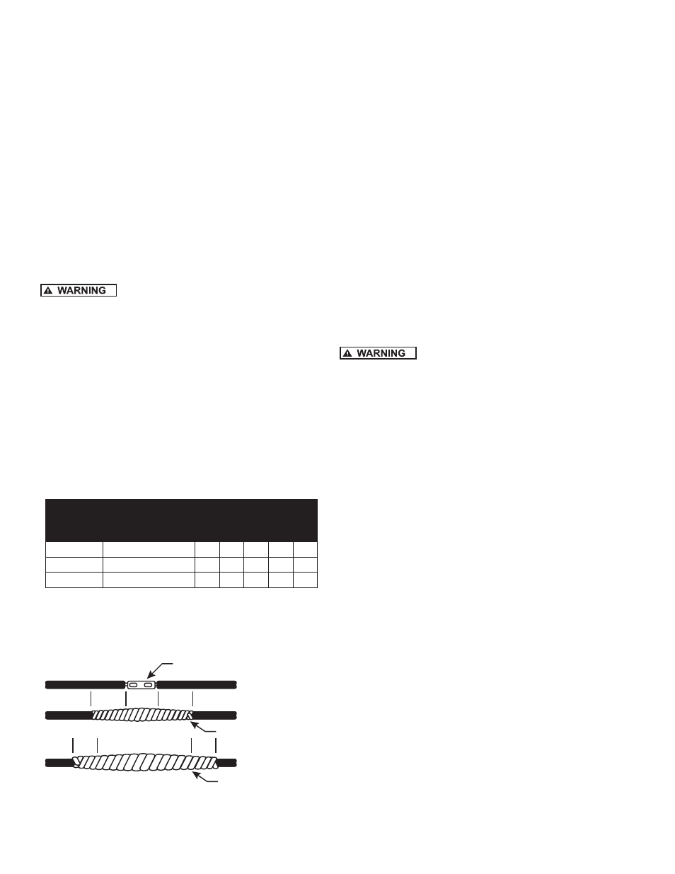
4. Splice motor leads to submersible cable with
commercially available potting, heat shrink splicing
kits or by careful tape splicing. Tape splicing should
use the following procedure.
Staked Connector
Rubber Tape
PVC Electrical Tape
2”
2”
2”
2”
IL0097
Figure 3
a) Strip individual conductor of insulation only as far
as necessary to provide room for a stake type
connector. Tubular connectors of the staked type are
preferred. If connector OD is not as large as cable
insulation, build-up with rubber electrical tape.
b) Tape individual joints with rubber electrical tape,
using two layers; the first extending two inches
beyond each end of the conductor insulation end,
the second layer two inches beyond the ends of the
first layer. Wrap tightly, eliminating air spaces as
much as possible.
c) Tape over the rubber electrical tape with #33
Scotch electrical tape, (Minnesota Mining Co.)
or equivalent, using two layers as in step “b” and
making each layer overlap the end of the preceding
layer at least two inches.
5. In the case of a cable with three conductors encased
in a single outer sheath, tape individual conductors as
described, staggering joints. Total thickness of tape
should be less than the thickness of the conductor
insulation.
GROUND WIRE INSTALLATION
Motor frame must be connected to power
supply ground or fatal electrical shock may result.
NOTE: All electrical wiring should be done by a
competent electrician.
1. Grounding the submersible pump is accomplished by
running a copper grounding wire from the pump motor
to the main electrical system ground.
2. The ground wire to be used must be of the same size
as the submersible power cable. It may be insulated
or bare. If insulated, it must be green, with or without
yellow stripe(s). The ground wire may be part of, or
separate from, the supply cable. It may be continuous
or spliced above the pump along with the supply
cable.
3. The motor lead wire assembly includes a green
insulated ground lead. Splice the ground wire to the
green insulated lead.
4. The other end of the ground wire will be connected to
the power supply grounding terminal or to the control
panel ground bar if it is connected to the power supply
ground.
NOTE: See section entitled Grounding for detailed
grounding instructions.
INSULATION AND CONTINUITY TEST
1. It is recommended that this test be done when the
splicing is complete and pump is being test run in
a tank of water. This test can be repeated after
installation in well but before the final electrical hook-
up is made to the control box or pressure switch.