Flint & Walling Commander Pro 75 User Manual
Page 3
3
95 North Oak Street • Kendallville, IN 46755
Copyright 2012. All Rights Reserved.
MAJOR WELL COMPONENTS
1. Submersible Pump — A submersible pump is a multi-
stage centrifugal. Each stage consists of an impeller
and diffuser. Water pressure increases in equal
amounts as it passes from stage to stage. The more
stages, the higher the pressure the pump will develop.
2. Submersible Motor — The submersible motor is
powered by three phase electricity. Make sure the
motor is designed for three phase operation.
3. Subdrive Controller — Subdrive is designed for use
in residential and light commercial applications with a
3-phase submersible motor using single-phase input.
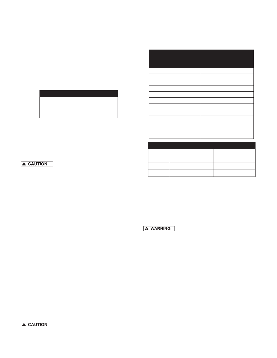
Motor Design Designation
Subdrive 75 Controller
1-1/2 HP
Subdrive 100 Controller
2 HP
Subdrive 150 Controller
3 HP
This variable speed controller can be used to provide
constant pressure delivery over a wide range of
settings (25 to 80 PSI). Factory preset is 50 PSI.
4. The Well — The well should be sand free and have a
sufficient flow of water to supply the pump. Clear well
of sand and any other foreign matter with a test pump
before installing the new submersible pump.
Using the submersible pump to clean the
well will void the warranty.
a. When drilling a new well in an area where sand is
a problem, a sand screen should be installed to
protect the pump and motor.
b. The well should be straight so damage during
installation does not occur to the pump or motor by
becoming lodged in a crooked well casing.
c. The complete pump and motor should be
submerged at least ten feet below the draw
down level of the well, and the motor should be a
minimum of ten feet off the bottom of the well.
5. The Piping — Install the pump with pipe of the same
diameter as the discharge port of the pump or larger.
NOTE: Use of pipe smaller than the discharge port of the
pump will restrict the capacity of the pump and lower its
operating performance.
6. Check Valve — A check valve is required on all
submersible installations. This valve maintains water
within the pipe when the pump is not running. A line
check should be installed within 25 feet of the pump
and below the draw down level of the water supply.
a. For well depths exceeding 200 feet, it is suggested
that an additional check valve be installed every
125 feet.
b. An additional check valve should be installed in the
horizontal line between the well top and the pressure
tank.
Make certain that the check valve is
pointing in the right direction, arrow pointing towards the
tank.
7. Torque Arrester — To center the pump as it is
being lowered into the well, a torque arrester is
recommended.
8. Pressure Tank — Any change to operating system
pressure will require that the precharge in the tank be
modified to 70% of that pressure.
Pressure Setting Guide
System Pressure
(at Pressure Sensor)
Pressure Tank Setting
(PSI) (+/- 2 psi)
25
18
30
21
35
25
40
28
45
32
50 (factory set)
35
55
39
60
42
65
46
70
49
75
53
80
56
Required Tank Size
10 gpm and smaller 19 gpm and larger
CP75
2 gallons
4 gallons
CP100
4 gallons
8 gallons
CP150
4 gallons
8 gallons
9. Pressure Relief Valve — The pressure relief valve and
the discharge outlet need a flow rating which exceeds
the flow capacity of the installation at the relief
pressure. When located in an area where a water leak
or relief valve blow-off may damage property, connect
an adequate drain line to the pressure relief valve.
Run the line to a suitable drain or to an area where
the water will not damage property.
Not providing an adequate relief valve
can cause extreme overpressure which could result in
personal and/or property damage. It is recommended that
you manually activate the valve monthly to keep it in good
working condition.
10. Pitless Adapter — A pitless adapter provides below
grade discharge while maintaining above grade
access to the well. Placed below the frost line they
are frost proof and also prevent well contamination by
providing a water tight seal between the vertical drop
pipe and the horizontal service pipe connection.
11. Well Seal — On well seal installations the piping in
the well projects above the well and is connected
above ground to the system piping by means of a tee
or elbow. Since the plumbing is above ground, it must
be protected from freezing.
12. Submersible Cable — Submersible power cable must
be UL listed for submersible pump application. Selecting
the proper cable size is important. Undersized cable
results in a too low voltage supply to the pump motor