Flint & Walling SP Self-Priming Sprinkler Pump User Manual
Page 2
2
© Copyright 2014 Flint & Walling. All rights reserved.
PREPARATION
Before beginning installation of product, make
sure all parts are present. Compare parts
with package contents drawing. If any part is
missing or damaged, do not attempt to assemble
the product. Contact customer service for
replacement parts.
Estimated Installation Time: 2 hours.
Tools Required for Assembly:
Hacksaw
Pipe Wrenches (2)
Wire Strippers
Needle-Nose Pliers
Phillips Screwdriver
Wire Cutters
Adjustable Wrench
Parts Required For Assembly:
2” foot valve or 2” suction strainer with check
valve
2 in. Sched 40 PVC pipe
1-1/2 in. Sched 40 PVC pipe
2 in. MPT x 2 in. slip adaptor
1-1/2 in. MPT x 1-1/2 in. slip adaptor
1-1/2 in. pipe tee
1-1/2 in. slip x 1-1/4 in. FPT reducer bushing,
1-1/4 in. MPT plug
2 in. 90º pipe elbow
1-1/2 in. 90º pipe elbow
thread tape
1/4 in. electric wire strain relief
2-step PVC glue system (primer and sealer)
Thread paste.
Optional Parts For Assembly (not included):
1. Priming Plug with Pressure Gauge: Used
instead of a priming plug alone. Helps
determine if the pump is primed, indicates if
the pump is operating properly and what kind
of pressure is in the system when operating.
a. (1) 1-1/4 in. MPT x 1/2 in. FPT reducer
bushing
b. (1) 1/2 in. MPT x 1/4 in. FPT reducer
bushing
c. (1) 100 PSI pressure gauge
2. Unions: Used for easy removal of the pump
from the sprinkler system.
a. (2) 2 in. union
b. (1) 1-1/2 in. union
3. (1) 1-1/2 in. Ball Valve: Prevents back flow
of water from the sprinkler system when the
pump is removed from the system.
4. 1-1/2 in. Couplers: Quantity determined by
the total length of pipe used.
5. 2 in. Couplers: Quantity determined by the
total length of pipe used.
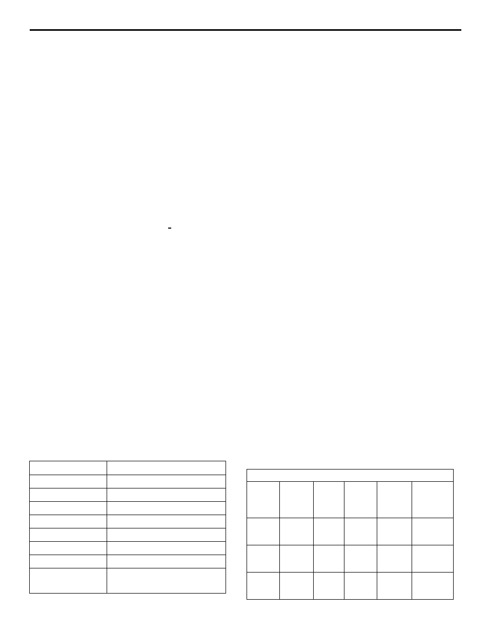
Component
Specifications
Pump housing
Heavy-duty, cast-iron
Diffuser
Thermoplastic
Impeller
Thermoplastic
Rotary seal
Carbon/silicon carbide
Mounting ring
Heavy-duty, cast-iron
Square cut ring
Buna-N
Base
Rigid steel
Motor
Dual voltage, double-ball
bearing
MOTOR DATA CHART
HP
Phase Volts
Code
Letter
Max
Amps
Locked
Rotor
Amps
1
1
1
115
230
H
17.6
8.8
62.0
31.0
1-1/2
1
1
115
230
G
18.00
9.00
72.0
36.0
2
1
1
115
230
G
21.00
10.50
108.0
54.0