One year limited warranty – Flint & Walling 4 (10 cm) Stainless Commander Plus S Series User Manual
Page 7
12
Copyright © 2014. All rights reserved • 95 North Oak St. • Kendallville, IN 46755
13
Copyright © 2014. All rights reserved • 95 North Oak St. • Kendallville, IN 46755
a. Three wire single phase: Yellow-Black indicates
main winding resistance; Yellow-Red indicates
start winding resistance.
b. Three phase: Resistance values should be equal
on all three phases: Yellow-Black; Yellow-Red;
Black-Red.
4. Correct readings should be equal to the Line-to-Line
resistance values from the specifications section for a
given motor, plus the resistance of the drop cable from
the table below.
5. Conditions:
Resistance (Ohms) Per 100 Feet of Copper Cable
(Round Trip)
AWG
14
12
10
8
6
4
2
0
Ohms
.5
.3
.2
.12
.08
.05
.03
.02
a. If one ohm value is less than specified, that
winding is shorted.
b. If one ohm value is greater than specified, that
winding is open, or there is a poor connection in
that circuit.
c. On 3-wire single phase, if one ohm value is
greater than specified and one ohm value is less
than specified, the leads are mixed. See the
section entitled “Cable Identification When Color
Code Is Lost.”
TESTING LOAD CURRENT AMPS
To test load current amps a clamp-on ammeter is
required. Since the ammeter measures current flow, the
motor must be running.
1. Pull the motor lead wire, being measured, (red, yellow
or black) away from all other wires.
2. Set ammeter to the highest scale. (If starting a motor
leave on the scale until current settles down).
3. Place tongs of meter around wire.
4. Change meter scale to one that gives the best
accuracy. This will be a reading between mid scale
and full scale.
5. Compare reading with current load amps on motors
data chart.
6. Test each motor lead.
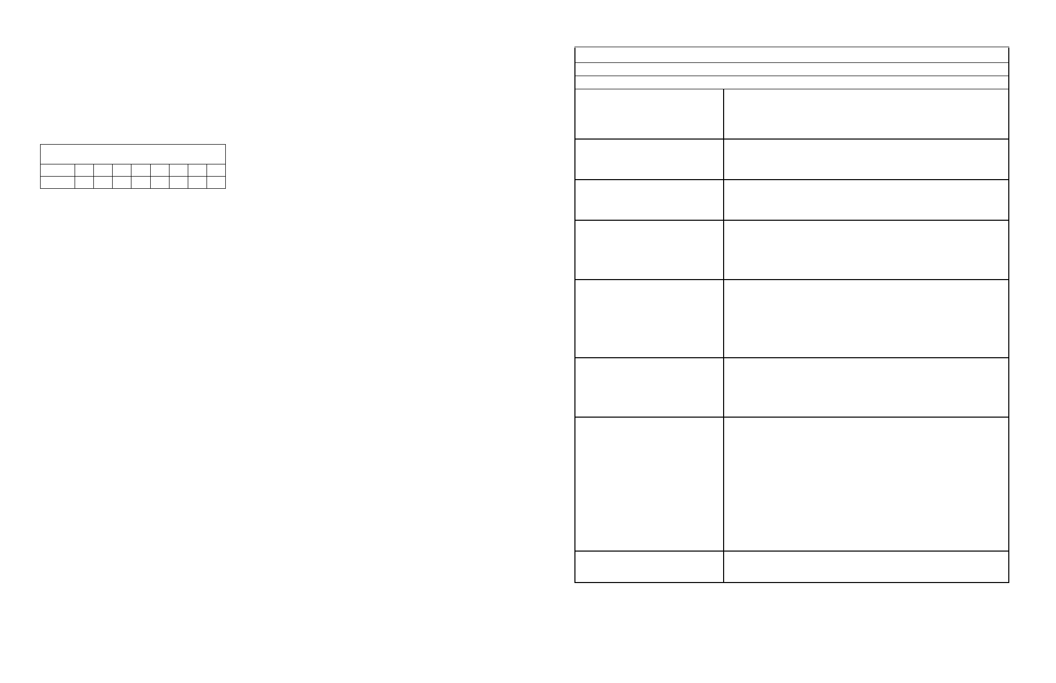
Single Phase Control Box Checking and Repairing Procedures
CAUTION: Turn power off and discharge capacitors before using ohmmeter.
TEST PROCEDURE
General Procedures
1. Disconnect line
2. Inspect for damaged or burned parts, loose connections, etc.
3. Check for misconnections against diagram in control box
4. If problem has not been found, check motor per Motor Data Chart and
control box as indicated below
Use of Ohmmeter
1. Ohmmeter such as Simpson Model #372 or #260, Triplett Model #630 or
#666 may be used
2. Whenever scales are changed, short ohmmeter leads and “zero balance”
meter
Ground (Insulation Resistance) Test
1. Ohmmeter Setting: Highest scale (usually R x 100K or 4 x 10,000)
2. Terminal Connections: One ohmmeter lead to “Ground” terminal on control
box and touch other lead to each of the other terminals on terminal board
3. Ohmmeter Reading: Pointer should remain at (∞) and not deflect
Overload Protector
1. Ohmmeter Setting: R x 1
2. Terminal Connections: Connect one ohmmeter lead to Terminal Black and
other lead to:
a. Terminal L
¹
in four-terminal boxes
b. Terminal L
²
in five-terminal boxes.
3. Ohmmeter Reading: Should be 0 to 0.5 ohms maximum
Capacitor Tests
1. Ohmmeter Setting: R x 1,000
2. Terminal Connections: One ohmmeter lead to relay terminal #1 and other to
black terminal on terminal board
3. Ohmmeter Reading: Pointer should swing toward “zero” and “float” back
to (∞). Capacitor is shorted if pointer does not move back to (∞), open if it
does not move from (∞)
4. If reading is not as above, disconnect capacitor from overload and test each
component
Relay Coil Test
(potential relays only)
1. Ohmmeter Setting: 4 x 1,000 (or R x 100)
2. Terminal Connections: #6 and #2 on Relay
3. Ohmmeter Reading:
For 230 Volt Boxes
G.E. 4.5 - 7.0 (4500-7000 ohms)
Cardinal 2.8 - 4.2 (2800-4200 ohms
Relay Contact Test
(potential relays only)
Most of the cases of inoperative relay contacts can be detected as follows:
1. Ohmmeter Setting: 4 x 1.
2. Terminal Connections: Terminal #1 and Terminal #2 on Relay.
3. Ohmmeter Reading: Should be “zero”.
NOTE: This test verifies “making” of contacts. If it is desired to test
“Opening” and closing of contacts:
a. Connect control box components in control box as indicated on diagram in
control box cover.
b. Connect three leads from motor of correct rating to control box terminal
board.
c. Connect power source voltage to L
¹
and L
²
.
d. Current in Red lead should momentarily be a high value - then drop
(within one second) to values on Motor Data Chart
1. Disconnect one coil lead.
Contactor Test
2. Ohmmeter setting R x 100.
3. Check coil resistance: 180 to 1400 ohms.
4. Remove contact cover and inspect contacts.
This product is warranted for one year from the date of purchase or two
years from the date of manufacture, whichever occurs first. Subject to the
conditions hereinafter set forth, the manufacturer will repair or replace to the
original consumer, any portion of the product which proves defective due to
defective materials or workmanship. To obtain warranty service, contact the
dealer from whom the product was purchased. The manufacturer retains
the sole right and option to determine whether to repair or replace defective
equipment, parts or components. Damage due to conditions beyond the
control of the manufacturer is not covered by this warranty.
THIS WARRANTY WILL NOT APPLY: (a) To defects or malfunctions
resulting from failure to properly install, operate or maintain the unit in
accordance with printed instructions provided; (b) to failures resulting
from abuse, accident or negligence or use of inappropriate chemicals or
additives in the water; (c) to normal maintenance services and the parts
used in connection with such service; (d) to units which are not installed in
accordance with normal applicable local codes, ordinances and good trade
practices; and (e) the unit is used for purposes other than for what it was
designed and manufactured.
RETURN OF WARRANTED COMPONENTS: Any item to be repaired
or replaced under this warranty must be returned to the manufacturer at
Kendallville, Indiana or such other place as the manufacturer may designate,
freight prepaid.
THE WARRANTY PROVIDED HEREIN IS IN LIEU OF ALL OTHER
EXPRESS WARRANTIES, AND MAY NOT BE EXTENDED OR MODIFIED
BY ANYONE. ANY IMPLIED WARRANTIES SHALL BE LIMITED TO
THE PERIOD OF THE LIMITED WARRANTY AND THEREAFTER ALL
SUCH IMPLIED WARRANTIES ARE DISCLAIMED AND EXCLUDED. THE
MANUFACTURER SHALL NOT, UNDER ANY CIRCUMSTANCES, BE
LIABLE FOR INCIDENTAL, CONSEQUENTIAL OR SPECIAL DAMAGES,
SUCH AS, BUT NOT LIMITED TO DAMAGE TO, OR LOSS OF, OTHER
PROPERTY OR EQUIPMENT, LOSS OF PROFITS, INCONVENIENCE, OR
OTHER INCIDENTAL OR CONSEQUENTIAL DAMAGES OF ANY TYPE
OR NATURE. THE LIABILITY OF THE MANUFACTURER SHALL NOT
EXCEED THE PRICE OF THE PRODUCT UPON WHICH SUCH LIABILITY
IS BASED.
This warranty gives you specific legal rights, and you may have other rights
which vary from state to state. Some states do not allow limitations on
duration of implied warranties or exclusion of incidental or consequential
damages, so the above limitations may not apply to you.
WARRANTY VALID IN CANADA AND MEXICO.
ONE YEAR LIMITED WARRANTY