Flint & Walling 4 (10 cm) Stainless Commander Plus S Series User Manual
Page 4
6
Copyright © 2014. All rights reserved • 95 North Oak St. • Kendallville, IN 46755
7
Copyright © 2014. All rights reserved • 95 North Oak St. • Kendallville, IN 46755
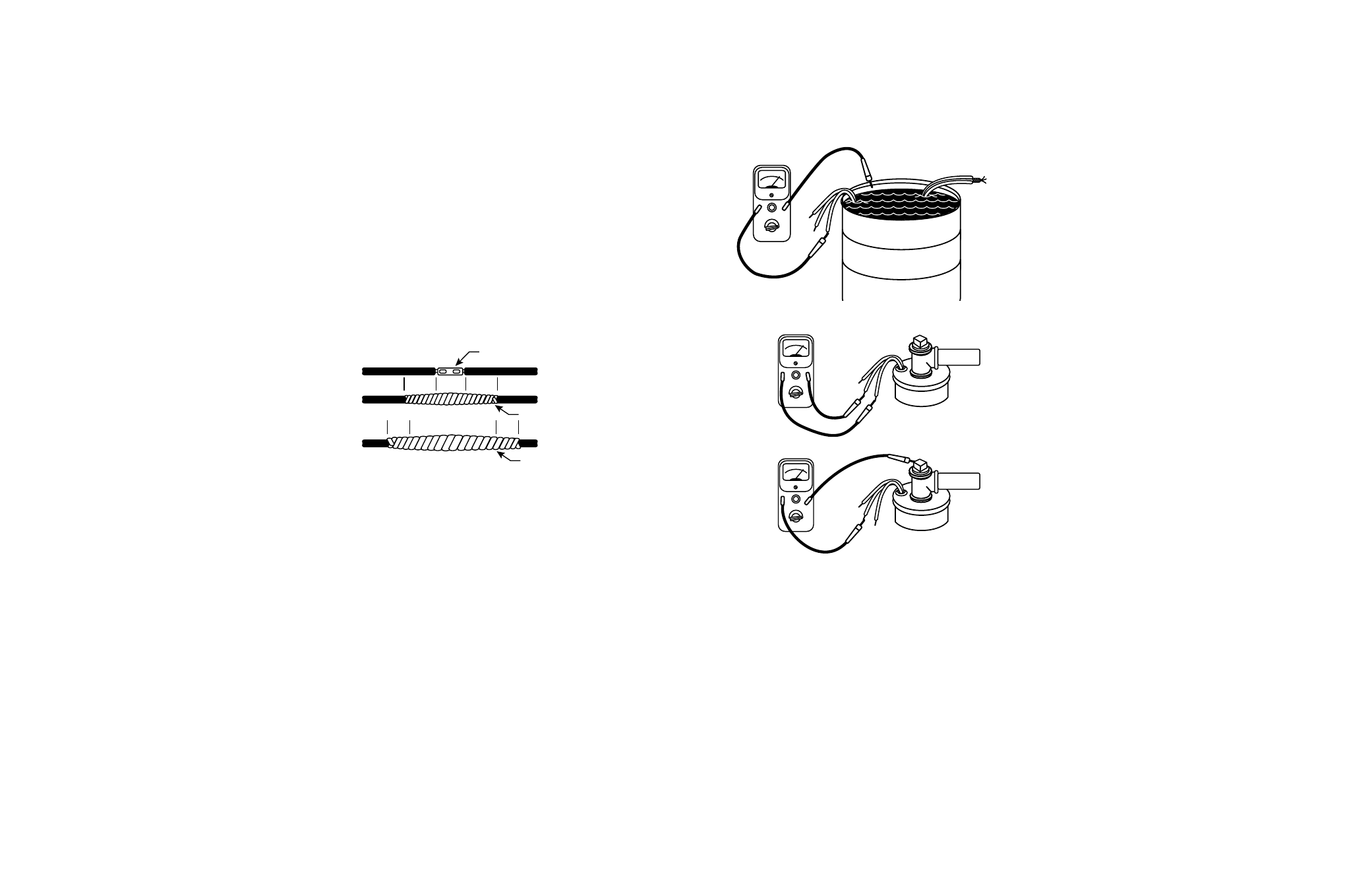
INSULATION AND CONTINUITY TEST
1. It is recommended that this test be done when the
splicing is complete and pump is being test run in
a tank of water. This test can be repeated after
installation in well but before the final electrical hook-
up is made to the control box or pressure switch (see
Figures 7 & 8).
IL0098
Figure 7
IL0099
Figure 8
2.
Zero the ohmmeter by clipping the leads together and
adjusting the zero ohm knob until the needle indicates
zero. Zero the ohmmeter before each use or every time
selector switch is changed.
3. Clip one ohmmeter lead to bare cable end.
4. Clip the other lead to edge of steel tank in which
pump and cable are submerged. If pump is already
in the well, clip lead to discharge pipe metal well
casing or bare ground wire.
5. A reading of less that 1,000,000 ohms indicates that
cable or splice is grounded. Slowly raise cable from
the water at the ohmmeter end. When trouble spot
moves clear of the water, needle will move toward
infinity reading. In an old installation with the pump in
the well, a reading of 20,000 ohms or less indicates
a breakdown in the insulation; in this case pull the
pump.
PUMP INSTALLATION
1. The following pump installation instructions use
Schedule 80 PVC pipe or galvanized pipe. If either
of these two types are used, a foot clamp or vise will
be required to hold the PVC or galvanized pipe when
connecting the next pipe length.
2. Install the pump in a well which is sand-free, straight,
and has sufficient flow of water to supply the pump.
Clear well of sand and any other foreign matter with a
test pump before installing the submersible pump.
NOTE: Using the submersible pump to clean the well
will void the warranty. When drilling a new well in an
area where sand is a problem, a sand screen must be
installed to protect the pump and motor.
3. Chlorinate the well first. Drop 24 to 48 HTH (chlorine)
tablets into the well before lowering the pump into the
well. This will prevent contamination and the growth
of iron bacteria which could later plug the well and the
pump. The chlorinated water will be pumped out of
the system when testing the pump flow.
4. BE SURE the top edge of the well casing is perfectly
smooth; sharp or jagged edges can cut or scrape the
cable and cause a short.
5. Install a line check valve within 25 feet of the pump
and below the draw down level of the water supply.
The check valve should be the same size as the
discharge outlet of the pump or larger.
NOTE: Use of pipe smaller that the discharge tapping of
the pump will restrict the capacity of the pump and lower
its operating performance.
6. When connecting the first length of pipe and
placing the pump in the well casing, care should be
maintained to center the pump in the well. It is easier
to handle the pump if a short piece of pipe is installed
first, rather than a long piece. Install the check valve
at the end of the first piece of pipe prior to lowering
the pump into the well. Maintain alignment as the
pump is placed and lowered into the well, a torque
arrester is recommended. Position the torque arrestor
to within 6” of the pump discharge and clamp arrestor
to pipe. Wrap the pipe with enough tape at top and
bottom of torque arrestor to keep it from sliding up the
pipe while the pump is being lowered into the well.
7. If not already done, splice the electrical cable to the
motor leads. The cable and ground wire should be
taped to the discharge pipe. Tape the cable about 5
feet above the discharge and every 20 feet thereafter.
Install cable guards if required to eliminate rubbing
against the well casing. Do not let the cable drag
over the edge of the well casing. Never allow the
weight of the pump to hang on the cable alone.
17. Pitless Adapter — A pitless adapter provides below
grade discharge while maintaining above grade
access to the well. Placed below the frost line they
are frost proof and also prevent well contamination
by providing a water tight seal between the vertical
drop pipe and the horizontal service pipe connection
(Figure 1).
18. Well Seal — On well seal installations the piping in
the well projects above the well and is connected
above ground to the system piping by means of a
tee or elbow. Since the plumbing is above ground, it
must be protected from freezing (Figure 2).
19. Submersible Cable — Submersible power cable
must be UL listed for submersible pump application.
Selecting the proper cable size is important.
Undersized cable results in a too low voltage supply to
the pump motor and ultimate motor failure. Oversized
cable is costly and not necessary. Refer to cable
selection chart for proper cable selection. Cable is
selected for the maximum pump setting plus the offset
distance to the service entrance.
20. Ground Wire — The National Electric Code (NEC 250-
43) requires a separate ground wire be run down the
well to the submersible pump and to be connected to
all exposed metal parts of the pump and motor. Refer
to the most recent National Electric Code (NEC) for
additional grounding information. All wiring should be
done by a competent electrician.
INSTALLATION
SUBMERSIBLE CABLE INSTALLATION
1. Check power source. Check electrical supply for
correct fusing, correct wire size, and adequate
grounding and transformer size.
WARNING: Since most submersible pump problems are
electrical, it is very important that all electrical work be
done properly. Therefore, all electrical hook-up work
or electrical service work should be done ny a qualified
electrician or serviceman only!
2. Follow wiring directions in the control box and make
momentary tests to see that the motor runs.
Do not
run pump dry for more than three (3) seconds. If
test is satisfactory, proceed to Step 3 (cable splice).
3. First check cable size against the Submersible
Wire Size Chart. Use extreme care; this is a very
important step. If required length falls between
two wire sizes, use the larger of the two wire sizes
(smaller number).
IMPORTANT: Use of wire sizes smaller than those
specified in the charts will cause low starting voltage,
may cause early pump failure and will void the warranty.
Larger wire sizes may always be used for better operating
economy.
4. Splice motor leads to submersible cable with
commercially available potting, heat shrink splicing
kits or by careful tape splicing. Tape splicing should
use the following procedure.
a) Strip individual conductor of insulation only as far
as necessary to provide room for a stake type
connector. Tubular connectors of the staked type
are preferred. If connector O.D. is not as large as
cable insulation, build-up with rubber electrical tape.
b) Tape individual joints with rubber electrical tape,
using two layers; the first extending two inches
beyond each end of the conductor insulation end,
the second layer two inches beyond the ends of
the first layer. Wrap tightly, eliminating air spaces
as much as possible.
c) Tape over the rubber electrical tape with #33
Scotch electrical tape, (Minnesota Mining Co.)
or equivalent, using two layers as in step “B”
and making each layer overlap the end of the
preceding layer at least two inches.
5. In the case of a cable with three conductors encased
in a single outer sheath, tape individual conductors as
described, staggering joints. Total thickness of tape
should be less than the thickness of the conductor
insulation.
GROUND WIRE INSTALLATION
WARNING: Motor frame must be connected to power
supply ground or fatal electrical shock may result.
IL0097
Staked Connector
Rubber Tape
PVC Electrical Tape
2”
2”
2”
2”
Figure 6
NOTE: All electrical wiring should be done by a
competent electrician.
1. Grounding the submersible pump is accomplished
by running a copper grounding wire from the pump
motor to the main electrical system ground.
2. The ground wire to be used must be of the same
size as the submersible power cable. It may be
insulated or bare. If insulated, it must be green, with
or without yellow stripe(s). The ground wire may be
part of, or separate from, the supply cable. It may be
continuous or spliced above the pump along with the
supply cable.
3. The motor lead wire assembly includes a green
insulated ground lead. Splice the ground wire to the
green insulated lead as shown in Figure 6.
4. The other end of the ground wire will be connected to
the power supply grounding terminal or to the control
panel ground bar if it is connected to the power
supply ground.
NOTE: See section entitled Grounding for detailed
grounding instructions.