Flint & Walling 4 (10 cm) Stainless Commander Plus S Series User Manual
Page 5
8
Copyright © 2014. All rights reserved • 95 North Oak St. • Kendallville, IN 46755
9
Copyright © 2014. All rights reserved • 95 North Oak St. • Kendallville, IN 46755
IL0100
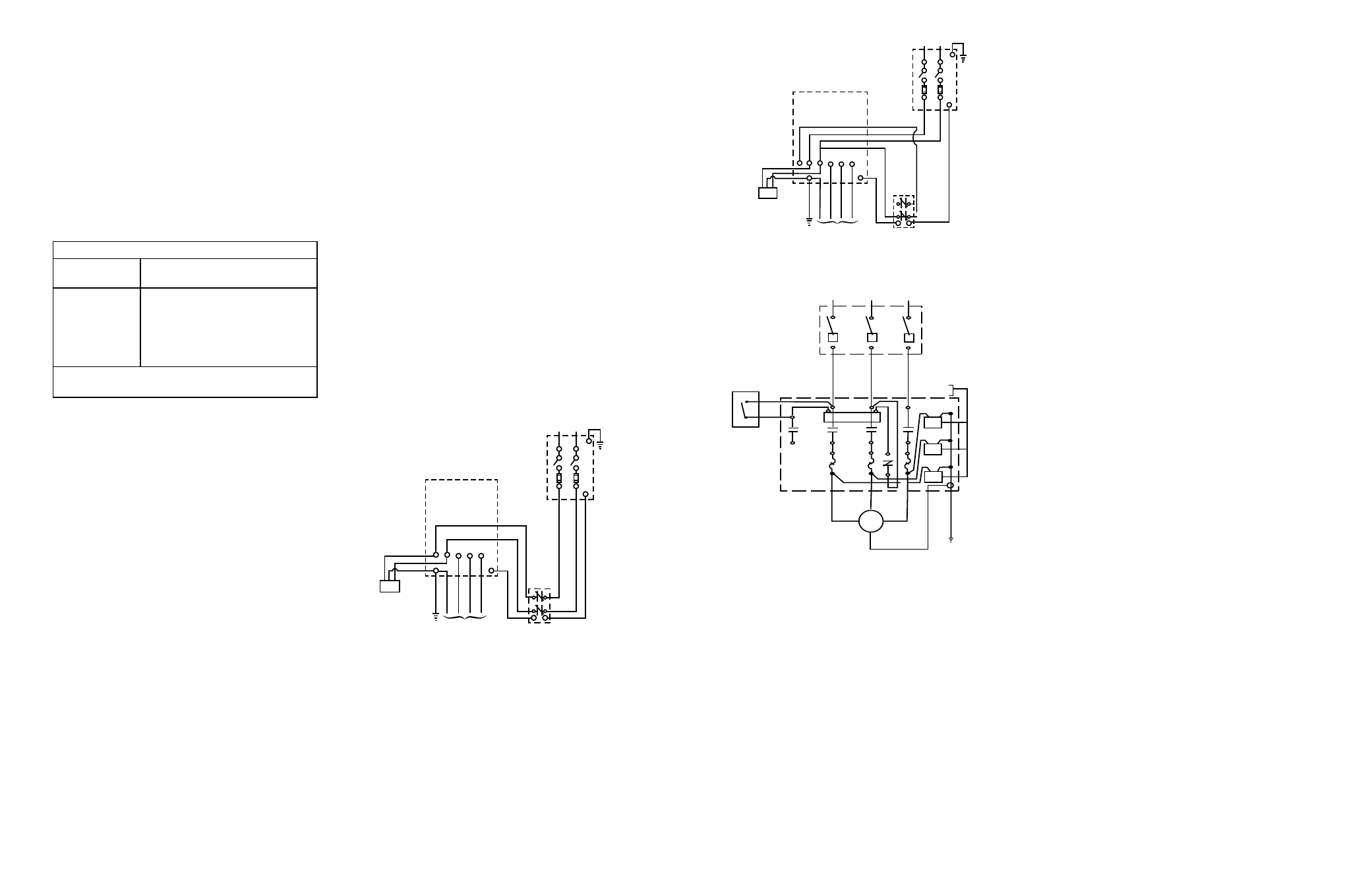
Fused Disconnect
Switch
Ground
Pressure
Switch
Ground
L1 L2
R Y B
Control Box
To Motor
Ground
Red
Yellow
Black
Lightning
Arrestor
SW
Figure 10 —
Single Phase Control Box with Contactor
IL0102
Pressure
Switch
3
2
L1
L2
L3
Fused Disconnect
Switch
Lightning
Arrestors
V
M
W
T1
T2 X2
T3
Motor
Ground
T3
T1
Figure 11 — Three Phase Magnetic Starter
1. For proper sizing of fuses for fuse disconnect box,
see Motor Data Charts. Improperly sized fuses will
result in fuses blown or circuit breakers tripped.
GROUNDING
Proper Grounding of Submersible Motors
1. The purpose of grounding any electrical apparatus is
to prevent an electrical shock hazard if exposed metal
becomes connected to an electrical circuit. This can
occur from a defect in construction of the electrical
equipment, physical damage, or a breakdown in the
insulation of the equipment. Grounding prevents
shock hazard by keeping exposed metal from
reaching a voltage level which could endanger
anyone coming in contact with the electrical
equipment. Fault current is “drained” by the ground
conductor, and if the fault is severe enough, the
circuit will be opened by the fuse or circuit breaker.
2. The U.S. National Electrical Code (NEC) requires that
motor-operated water pumps, including submersible
type regardless of voltage, shall be grounded. The
Canadian Electrical Code specifically discusses
grounding requirements for submersible pumps.
Interpretation of these and other codes may vary
in different states and localities, but all applicable
national, state, and local codes should always be
followed.
3. Any submersible motor which is to be run tested out
of the well should be grounded to prevent possible
shock hazard during the test.
NOTE: Always disconnect all power when making
ohmmeter check and while pulling or installing a pump.
4. The most logical way to “frame” ground a submersible
motor is normally as follows:
a. Run an extra wire with the motor power conductors.
This wire must be sized to meet Table 250-95 in the
U.S. National Electrical Code. If code information
is unavailable, using the same size wire as the
power conductors is normally adequate.
b. The ground wire may be insulated or bare. If
insulated, it must be green with or without yellow
stripe(s). The ground wire may be part of, or
separate from the supply cable. It may be
continuous or spliced above the pump along with
the supply cable.
c. Connect the green or bare ground wire to the
green ground wire of the submersible motor lead
assembly. If the lead wire assembly does not
include a separate ground wire, attach a lug to
the ground wire and place the lug over one of the
motor studs above the pump intake flange so the
pump will not be cocked. The ground lug will then
be secured with the nut which holds the pump on
the motor.
d. Connect the other end of the ground wire to the
power supply grounding terminal or to the control
panel ground bar if it is connected to the power
supply ground.
e. All connections should be tight and corrosion
resistant, including screws, lugs or clamps.
Grounding Control Boxes
1. It is recommended the control box grounding terminal
always be connected to circuits which include a
grounding conductor. In fact, this is a requirement
of the National Electrical Code. If the circuit has no
grounding conductor and no metal conduit from the
box to supply panel, use a wire at least as large as
line conductors and connect from supply panel to the
control box and to the motor lead ground wire.
WARNING: Failure to ground the box frame can result in a
fatal electrical shock hazard if a circuit fault occurs.
WARNING: Serious or fatal electrical shock may result
from failure to connect all metal plumbing, and the motor
if outside a drilled well, to the power supply grounding
terminal with wire no smaller than motor cable wires. Do
not use motor in swimming area.
8. Lower the pump into the well slowly without forcing.
Use a vise or foot clamp to hold the pipe while
connecting the next length. A boom, tripod or
pump setting rig is recommended. Lower pump to
approximately 10 feet below maximum draw down
of the water if possible and keep approximately 10
feet from the bottom. DO NOT set pump on bottom
of well. Before each new length of pipe is added,
attach the coupling to the top of the pipe length. This
will provide a stop for the foot clamp to hold while the
next section of pipe is being installed.
9. On a standard tank with an air volume control a
bleeder orifice is required. Install the bleeder orifice
in the discharge pipe 5 feet or more below the snifter
valve. See Figure 2 and the table below.
Distance Table
Tank Size
Gallons
Depth From Horizontal Check
Valve To Bleeder Orifice
42
82
120
220
315
525
5
10
15
15
20
20-35
Installations that use a pre-charged pressure tank
do not require a bleeder orifice.
WELL SEAL/PITLESS ADAPTER INSTALLATION
1. All installations should have a well seal. Make sure
the seal is seated and tighten the bolts evenly.
NOTE: Be sure to assemble the tee to the pipe above
the well seal to prevent dropping the pipe and pump
down the well as you lower it.
IMPORTANT: Well seal and piping must be protected
from freezing.
2. On a pitless adapter installation, the connection to the
system supply line is made below ground. Install the
pitless adapter following the instructions included with
particular brand or design being used in the installation.
NOTE: Follow ALL applicable state and local plumbing
codes.
PRELIMINARY TEST RUN
1. When pump is at desired depth, install throttle valve
for preliminary test run. Wire single phase motors
through the control box, following instructions in box
regarding color coding of wires, etc. Wire 3-phase
motors through a magnetic starter. Test cable for
continuity with an ohmmeter.
2. With pump discharge throttled, run pump until water
is clear of sand or any other impurities. Gradually
open discharge.
CAUTION: Be sure you do not stop pump before water
runs clear. This may take several hours. If pump stops
with sand in it, it will lock.
3. If pump lowers water in the well far enough to lose
prime, either lower pump in the well (if possible) or
throttle discharge to capacity of the well.
4. If well is low capacity, use a low water level control.
5. On 3-phase units, establish correct motor rotation
by running in both directions. Change rotation by
exchanging any two of the three motor leads. The
rotation that gives the most water flow is always the
correct rotation.
PRESSURE TANK INSTALLATION
1. On a new installation, install the pressure tank along
with the pressure switch, pressure gauge, pressure
relief valve, check valve, gate valves and unions as
shown in Figures 1 & 2.
2. On replacement pump installations be sure that the
tank system is in good operating condition, as a
water logged tank may cause pump failure.
ELECTRICAL HOOK-UP
WARNING: Since most submersible pump problems are
electrical, it is very important that all electrical work be
done properly. Therefore, all electrical hook-up work
or electrical service work should be done by a qualified
electrician or serviceman only!
WARNING: Always disconnect power source before
working on or near motor, its connected load or control
box and wiring. If the power disconnect is out of sight,
lock it in the open position and tag to prevent unexpected
application of power.
1. Proceed with electrical hook-up matching cable colors
and following the wiring diagrams (Figures 9, 10 &11)
or inside the lid of the control box.
WARNING: Connect motor leads momentarily for correct
rotation before installing pump in well.
FUSE SIZES
Fused Disconnect
Switch
Ground
Pressure
Switch
Ground
L1 L2
R Y B
Control Box
To Motor
Ground
Red
Yellow
Black
Lightning
Arrestor
IL0100
Figure 9 — Single Phase Control Box