Flint & Walling 4 (10 cm) Stainless Commander Plus S Series User Manual
Page 3
4
Copyright © 2014. All rights reserved • 95 North Oak St. • Kendallville, IN 46755
5
Copyright © 2014. All rights reserved • 95 North Oak St. • Kendallville, IN 46755
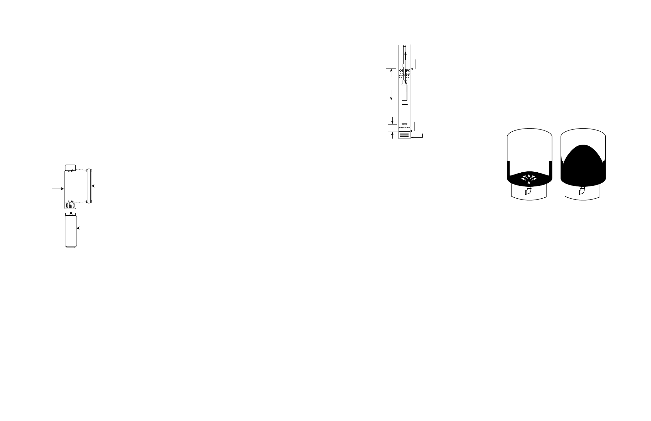
8. The complete pump and motor should be submerged
at least twenty feet below the draw down level of the
well, and the motor should be a minimum of ten feet
off the bottom of the well (Figure 4).
Drawdown
Water Level
10 Ft. Min.
20 Ft.
Top of Well Screen
Bottom of Well
Figure 4
9. The Piping — Install the pump with pipe of the same
diameter as the discharge port of the pump or larger.
NOTE: Use of pipe smaller that the discharge port of the
pump will restrict the capacity of the pump and lower its
operating performance.
10. Check Valve — A check valve is required on all
submersible installations. This valve maintains water
within the pipe when the pump is running. A line check
should be installed within 25 feet of the pump and
below the draw down level of the water supply.
a. For well depths exceeding 200 feet, it is suggested
that an additional check valve be installed every
100 feet.
b. An additional check valve should be installed in the
horizontal line between the well top and the pressure
tank (See Figures 1 & 2).
CAUTION: Make certain that the check valve is pointing in
the right direction, arrow pointing towards the tank.
11. Torque Arrester — To center the pump as it is
being lowered into the well, a torque arrester is
recommended. This will also minimize the pump
whipping due to the starting torque of the motor (See
Figure 2).
NOTE: On plastic pipe installations a torque arrester
must be installed. Cable guards should also be installed.
12. Pressure Tank — The purpose of the pressure tank
is to allow an amount of water to be drawn before the
pressure drops enough to cause the pump to start.
Without a pressure tank, the pump would start and
stop continuously when water is drawn. There are
two types of pressure tanks, the standard tank that
requires an air volume control and the pre-charged
tank.
a. On a standard pneumatic tank system, air is
introduced to compensate for that which is
absorbed by the water. Each time the pump
cycles air is added to the tank through a bleeder
and snifter valve. The excess air is released by
a float assembly (air volume control) in the upper
side tapping of the tank (See Figure 2).
b. In a pre-charged tank, a flexible diaphragm or
bladder separates the air and water areas of the
tank. The air chamber is pre-charged by means of
a tire valve with pressure 2 PSI less than the cut-
on pressure of the pump. Because the air is not
in contact with the water, it cannot be absorbed by
the water. Therefore, the original charge of air is
never lost.
13. In pre-charged tank systems, none of the fittings for
air introduction or air level control are required (Figure
1). The piping in the well is also different for the two
systems. The pre-charged tank system does not
require a bleeder orifice assembly, which simplifies
the installation.
IL0096
Pump on.
Water enters
the reservoir
System Filled.
Pump Off
Figure 5
14. The tank size should be selected to keep the pump
starts per day as low as practical for maximum life.
Excessive motor cycling accelerates motor bearing
and spline wear, pump wear and contact erosion.
Use as a guide, 100 starts per day (24 hours) on
single phase motors and 300 starts per day on three
phase units.
15. Pressure Switch — The pressure switch provides
for automatic operation. The pump starts when the
pressure drops to the switch cut-in setting and stops
when the pressure reaches the switch cut-out setting.
The pressure switch must be installed as close to the
tank as possible (Figures 1 & 2).
16. Pressure Relief Valve — A properly sized pressure
relief valve must be installed on any installation where
the pump pressure can exceed the pressure tank’s
maximum working pressure or on systems where
the discharge line can be shut off or obstructed. The
relief valve drain port should be piped to a drain
(Figures 1 & 2).
WARNING: Not providing a relief valve can cause extreme
over pressure, which could result in personal and/or
property damage.
ASSEMBLY
CAUTION: Be sure pump size corresponds with
horsepower size of motor. If pump size exceeds
recommended motor, overloading of motor and damage to
the motor could result.
1. If not yet assembled, check that the pump and motor
mounting faces are free from dirt.
2. Assemble the pump liquid end and motor together
so that mounting faces are in contact. Then tighten
assembly bolts evenly.
NOTE: Apply non-toxic FDA approved waterproof grease
such as Mobile 102, Texaco CYGNUS2661 or equivalent
to the coupling before assembly of pump coupling to
motor shaft. This will prolong spline life and prevent
abrasives from entering the spline area.
3. Check for free rotation of the pump and motor. A
slight drag is permissible.
4. Assemble the pump lead guard over the motor leads.
CAUTION: Do not cut or pinch lead wire during assembly.
5. Assemble suction screen to pump mounting ring.
Liquid
End
Lead Wire
Guard
Motor
IL0094B
Figure 3
PRE-INSTALLATION
To save possible added expense and extra trips, observe
and complete as many as possible of the following
precautions and pre-installation procedures before going
to the job site or beginning the installation.
IMPORTANT PRECAUTIONS
1. Prior to installation, inspect the pump for damage.
Check for free pump and motor rotation. A slight
drag is permissible.
2. Check to make certain that the voltage of the motor
end and control agree with the available phase and
voltage. Check power source. Check electrical
supply for correct fusing, correct wire size, and
adequate grounding and transformer size.
WARNING: Since most submersible pump problems are
electrical, it is very important that all electrical work be
done properly. Therefore, all electrical hook-up work
or electrical service work should be done by a qualified
electrician or service man only!
3. Throughout installation, take care not to damage
the insulation of the electrical cable or motor leads.
Never support the weight of the unit by electrical
cable or motor leads.
4. Before the pump is installed, the well should be
pumped free of sand and other foreign matter with
a test pump.
The warranty is void if it is used to
clean the well.
5. Follow wiring directions in the control box and make
momentary tests to see that motor runs. (It is normal
to hear some noise from the pump when you are
momentarily testing it).
Do not run pump dry for
more than three (3) seconds.
MAJOR WELL COMPONENTS (see Figures 1 & 2)
1. Submersible Pump — A submersible pump is a multi-
stage centrifugal. Each stage consists of an impeller
and diffuser. Water pressure increases in equal
amounts as it passes from stage to stage. The more
stages, the higher the pressure the pump will develop.
2. Submersible Motor — Submersible pumps can
be powered by either single phase or three phase
motors. Make certain that the motor corresponds
with the horsepower required by the pump. Failure
to do so, could result in overloading of the motor and
motor damage.
3. Control Box — Single phase submersible motors
require the use of an above ground control box for
starting. Operation of these motors without control
boxes or with incorrect boxes can result in failure of
motors which will void the warranty.
4. Magnetic Starters and Overload Protection —
Three phase submersible motors require the use
of an above ground magnetic starter and overload
protection. Operation of these motors without or
incorrect starters and protectors will result in the
failure of motor which will void the warranty. See
Magnetic Starter Chart for the correct selection of
magnetic starters and ambient compensated quick
trip protectors.
5. The Well — The well should be sand free and have
a sufficient flow of water to supply the pump. Clear
well of sand and any other foreign matter with a test
pump before installing the new submersible pump.
CAUTION: Using the submersible pump to clean the well
will void the warranty.
6. When drilling a new well in an area where sand is a
problem, a sand screen should be installed to protect
the pump and motor.
7. The well should be straight so damage during
installation does not occur to the pump or motor by
becoming lodged in a crooked well casing.
READ THESE INSTRUCTIONS COMPLETELY BEFORE INSTALLATION