9 maintenance and care, 10 disassembly, 11 troubleshooting – Festo DAPS..R..-F.. User Manual
Page 4: 12 technical data
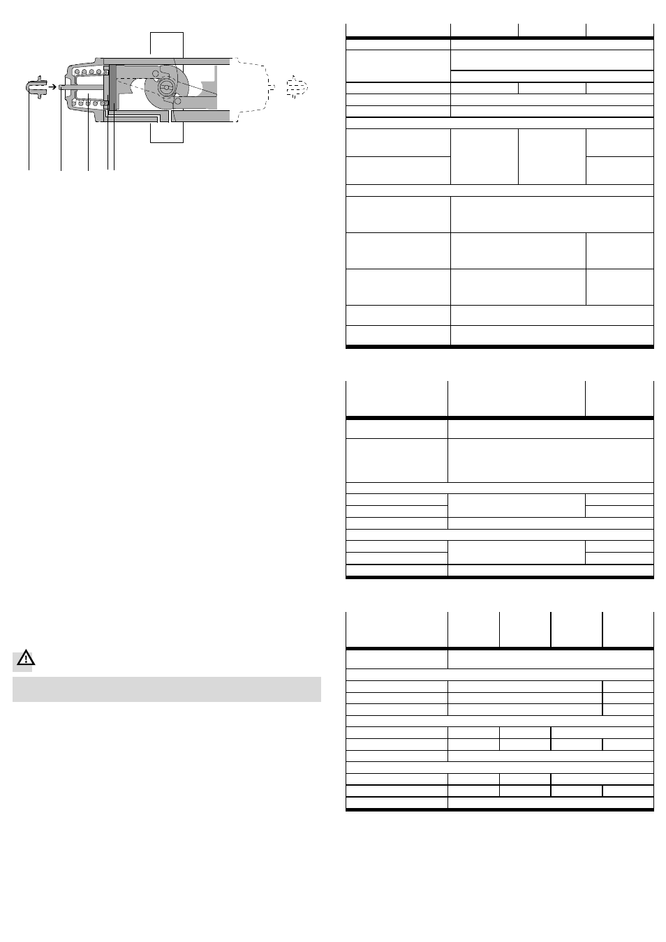
End position for left turning – opening process valve
1
2
3 4
5
1 Lock nut with sealing ring
2 Threaded rod
3 Adjustment range of the outer end
position (see technical data)
4 Spring disc
5 Piston
Fig. 10
1. Supply compressed air and open the process valve. The pistons move to the
outer end position. This fixes the threaded rods, if necessary – dependent on the
current setting. Loosening of the lock nuts will then not accidentally change the
current setting.
2. Screw down the lock nuts with sealing ring on both sides. If the threaded rods
have loosened, retighten them by hand until a light resistance is felt.
3. Vent the DAPS and close the process valve. The pistons move to the inner end
position.
4. Adjust the end position:
Observe that a complete turn of the threaded rod can change the swivel angle
approx. 1.5° to 3.5° – dependent on the product design.
– Turning threaded rods clockwise reduces the swivel angle.
– Turning threaded rods anti-clockwise increases the swivel angle.
• Turn both threaded rods equally far so they stop the pistons in operation
simultaneously.
5. Supply compressed air and open the process valve. The pistons run against the
threaded rods into the outer end position.
6. Check the position of the process valve. To change the swivel angle, repeat
steps 3 to 6
7. If the desired position is found, check whether both threaded rods offer resist-
ance to the pistons in the opened process valve position. If necessary, screw in
loose threaded rods carefully until resistance is felt.
8. Screw the lock nuts back onto the threaded rods – tightening torque 5 Nm.
9. Check the mode of operation of the quarter turn actuator (
section 8.4)
8.4 Check the mode of operation of the quarter turn actuator
• Check in cyclical tests, through alternating pressurisation and, if necessary,
venting, whether the quarter turn actuator takes the required positions.
• If necessary, adjust the end positions to the extent the quarter turn actuator
offers this possibility (
section 8.1).
9
Maintenance and care
If used as intended in the operating instructions, the device will be maintenance-
free.
10
Disassembly
Warning
Danger of injury due to uncontrolled movements.
• Switch the tubing system pressureless before dismantling.
1. If necessary, remove any existing limit switches.
2. Remove the pneumatic switching valve.
3. Loosen the screws on the flange of the process valve.
4. Remove the quarter turn actuator (if necessary including mounting adapter and
coupling extension) from the process valve.
11
Troubleshooting
• Please contact Festo.
12
Technical data
General technical data
DAPS-...
DAPS–...–T6
DAPS–...–CR
Operating medium
Compressed air to ISO8573-1:2010 [7:4:4]
Note about the
operating medium
Operation with lubricated medium possible (required in further
operation)
Ester oil < 0.1 mg/m³, corresponds to ISO 8573:2010 class [-:-:2]
Ambient temperature
[°C]
–20 … +80
–50 … +60
–20 … +80
Swivel angle
[°]
90
Mounting position
Any
Valve connection corresponding to standard
– DAPS-0008-…
– …
– DAPS-0030-...
VDI/VDE 3845
(NAMUR)
VDI/VDE 3845
(NAMUR)
–
– DAPS-0053-…
– …
– DAPS 8000
VDI/VDE 3845
(NAMUR)
Pneumatic connection
– DAPS-0015..RS to
DAPS-0180..RS..
– DAPS-0008..R- to
DAPS-0360..R-..
G1/8
– DAPS-0240..RS to
DAPS-0960..RS..
– DAPS-0480..R- to
DAPS-1920..R-..
G1/4
G1/8
– DAPS-1440..RS to
DAPS-4000..RS..
– DAPS-2880..R- to
DAPS-8000..R-..
G3/8
–
Standard connection
to the process valve
ISO 5211
CE marking (see declaration of
conformity
www.festo.com)
in accordance with EU Explosion Protection Directive (ATEX)1)
1)
Certification-specific special documentation and the documentation of the sensors must be considered
www.festo.com
Operating conditions
DAPS..RS-…
(single-acting)
DAPS-
0015 … 0960
DAPS-
1440 … 4000
Nominal operating
pressure
[bar]
5.6
Operating pressure
1)
– DAPS..RS1-...
– DAPS..RS2-...
– DAPS..RS3-...
– DAPS..RS4-...
[bar]
2.8 ... 8.4
3.5 ... 8.4
4.2 ... 8.4
5.6 ... 8.4
End-position adjusting range at 0°
– DAPS..RS-...
[°]
One end position adjustable; -1 … +9
±5
– DAPS..RS-...-T6
[°]
±5
– DAPS..RS-...-CR
[°]
–
End-position adjusting range at 90°
– DAPS..RS-...
[°]
One end position adjustable; 81 … +91
85 … +95
– DAPS..RS-...-T6
[°]
85 … +95
– DAPS..RS-...-CR
[°]
–
1)
Minimum operating pressures vary for single-acting quarter turn actuators dependent on the number of
springs
Operating conditions
DAPS..R-...
(double-acting)
DAPS-
0008
DAPS-
0015 …
1920
DAPS-
2880 …
5760
DAPS-
8000
Nominal operating
pressure
[bar]
5.6
Operating pressure
1)
– DAPS..R-...
[bar]
1 ... 8.4
1 ... 7
– DAPS..R-...-T6
[bar]
3.5 ... 8.4
–
– DAPS..R-...-CR
[bar]
2.5 ... 8.4
–
End-position adjusting range at 0°
– DAPS..R-...
[°]
–
-1 … +9
±5
– DAPS..R-...-T6
[°]
–
-1 … +9
±5
–
– DAPS..R-...-CR
[°]
–
End-position adjusting range at 90°
– DAPS..R-...
[°]
–
–
85 … +95
– DAPS..R-...-T6
[°]
–
–
85 … +95
–
– DAPS..R-...-CR
[°]
–
1)
Exceptions for devices with special marking