7 installation, 1 mechanical installation, 2 pneumatic installation – Festo DAPS..R..-F.. User Manual
Page 2: Connections for the compressed air supply
• Take into consideration the ambient conditions at the location of use. Corrosive
environments reduce the service life of the product.
• Remove the packaging except for the adhesive labels on the compressed air
supply ports (danger of contamination). The material used in the packaging has
been specifically chosen for its recyclability (exception: oil paper = residual
waste).
• Use the product in its original status, without any unauthorised product modific-
ations.
• Protect the device from pressure fluctuations. Use excess-pressure and pres-
sure-regulating valves.
• Make sure the compressed air is properly prepared (Technical data
section 12).
• Before carrying out installation, dismantling and maintenance work, switch off
the compressed air supply and vent the actuator. Secure compressed air supply
against accidental restarting.
Danger
In the case of single-acting DAPS, high spring forces (mechanically stored en-
ergy) are at work inside the product.
Parts can be ejected and cause serious personal injuries if the end cap is dis-
mounted.
• Never remove the end cap!
• Return the product to Festo if defective or for service.
Note
• Use only unlubricated compressed air under normal conditions.
The DAPS quarter turn actuator possesses an initial lubrication which suffices
for the complete service life.
Note
Continuous operation at the limits of the specified ambient temperature and
work frequency can reduce the service life of the quarter turn actuator.
• Use lubricated compressed air for continuous operation under extreme con-
ditions. The oil must be chemically inert and must not carbonise.
If lubricated compressed air is used:
The initial lubrication will be washed out. The quarter turn actuator may then
only be operated with lubricated compressed air.
7
Installation
Note
The following instructions on fitting the DAPS quarter turn actuator onto a pro-
cessing valve may only be used if the following requirements are met:
– The quarter turn actuator is installed in the direction of the tubing.
– If a 2-way process valve is used:
The 2-way process valve is closed.
– If a 3-way process valve is used:
The switching status of the 3-way process valve is known.
Note
If a 3-way processing valve is used:
• Align the quarter turn actuator so that the port openings for a NAMUR valve
face the side without tubing.
Note
Outflowing processing medium must not ingress into the quarter turn actuator.
The housing of some quarter turn actuators has a leakage groove on the process
valve port side. If the processing valve leaks, the leakage can flow through the
open groove.
• For housings with leakage grooves, make sure that the groove (
Fig. 1,
9 )
is not sealed. In this way you can be sure that neither processing medium nor
escaping air from the processing valve can penetrate into the quarter turn
actuator.
The DAPS quarter turn actuator can be mounted with or without an adapter bridge.
If there are high media temperatures in the tubing and in processing valve:
• Use an adapter bridge and also a heat-insulated coupling extension.
7.1 Mechanical installation
• In order to mount the DAPS quarter turn actuator, set the switching shaft of the
process valve so that the desired operating method for opening and closing the
process valve is implemented.
• Note that a processing valve with butterfly valve can only be opened in one dir-
ection and closed in the opposite direction.
• Observe the tightening torque
Thread
M5
M6
M8
M10
M12
M14
M16
M20
Tightening torque
[Nm]
5 …
6
10 …
11
20 …
23
45 ...
50
80 …
85
125 …
135
190 …
200
370 …
390
Fig. 5
To mount the quarter turn actuator without an adapter
bridge:
1. Place the quarter turn actuator on the switching
shaft of the process valve. Make sure here that the
square of the processing valve sits in the
star-shaped coupling of the quarter turn actuator
without being tilted.
Fig. 6
2. Fasten the quarter turn actuator with 4 corrosion-
resistant screws and retaining rings (material: VA)
to the connection flange of the process valve.
3. Tighten all the screws in diagonally opposite
sequence. Tightening torque
Fig. 5.
4. Continued
Point 6.
To mount the quarter turn actuator with an adapter
bridge, you need:
Fig. 7
1
2
– an adapter bridge (
Fig. 7,
1 ),
– a shaft extension (
Fig. 7
2 ).
1. Align the adapter bridge so that its supports are
oriented in the direction of the longitudinal axis of
the quarter turn actuator and, if necessary, the
open side of the adapter bridge towards the pro-
cess valve.
2. Fasten the adapter bridge to the quarter turn actu-
ator. But do not tighten the screws yet.
3. Guide the shaft extension through the adapter
bridge into the star-shaped coupling on the
bottom of the quarter turn actuator. Make sure
that the shaft extension sits in the coupling
without being tilted.
4. Fasten the quarter turn actuator with adapter bridge and shaft extension to the
connection flange of the process valve. Make sure here that the square of the
process valve sits in the shaft extension without being tilted.
5. Tighten all the screws in diagonally opposite sequence.
Tightening torque
Fig. 5.
After attachment of the quarter turn actuator:
6. Check in cyclical tests whether the quarter turn actuator turns in the required
direction of rotation and whether the process valve takes the required position.
7. If the quarter turn actuator does not turn in the required direction of rotation:
Carry out the following modification:
DAPS..R-… (double-acting)
DAPS..RS-… (single-acting)
1. Remove the pneumatic solenoid valve.
2. Turn the solenoid valve 180°.
3. Note the position of the threaded pin for
orientation of a NAMUR valve.
4. Fasten the solenoid valve again.
1. Remove the screws on the actuator side.
2. Turn the actuator 90° while it is still connec-
ted through the shaft extension or directly to
the processing valve.
3. Tighten the mounting screws.
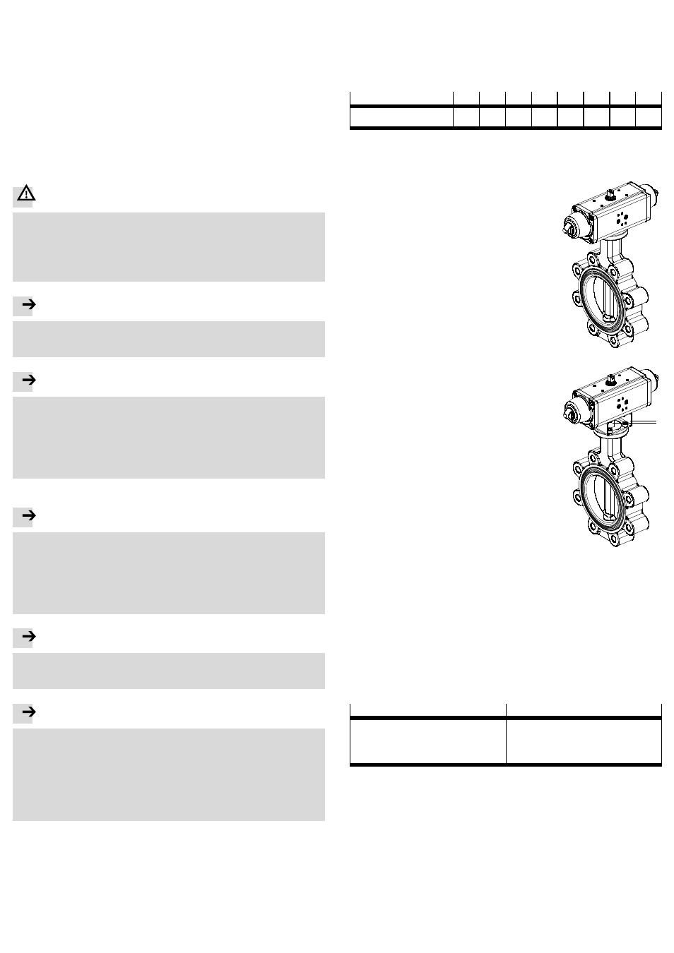
7.2 Pneumatic installation
Connections for the compressed air supply
DAPS quarter turn actuator, double-acting:
– Air supply at port 2 (A) – see Fig. 1,
2
Rotational movement of the switching shaft in an anti-clockwise direction.
– Air supply at port 4 (B) – see Fig. 1,
4
Rotational movement of the switching shaft clockwise.
DAPS quarter turn actuator, single-acting (spring return):
– Air supply at port 4 (B): rotational movement anti-clockwise.
– Spring return: rotation clockwise.