3 installing circuitry, 8 commissioning, 1 adjustment of the end positions – Festo DAPS..R..-F.. User Manual
Page 3
Note
For DAPS..RS-… (single-acting):
• Fasten a filter element to the exhaust port 2 (A) to prevent ingress of dirt
particles.
7.3 Installing circuitry
Using the pneumatic switching valves:
• Please note the instructions and explanations in the relevant operating instruc-
tions for the pneumatic valves.
8
Commissioning
Note
• Make sure that the operating conditions
section 12 lie within the permissi-
ble ranges.
The product is ready for operation as soon as it is installed and connected.
• Make sure that a process valve attached to the quarter turn actuator can be
switched without hindrance.
• Slowly pressurize the quarter turn actuator at first. For slow start-up pressurisa-
tion use soft-start valve type HEL.
8.1 Adjustment of the end positions
Some product variants offer the possibility to adjust one or even both end posi-
tions of the DAPS within narrow limits in order to influence the closing or opening
angle of the mounted process valve. During adjustment of the end positions, ob-
serve the permissible adjustment range of the DAPS used (
section 12, end
position adjustment range).
Note
Product variants without specification of an adjustment range have
no possibility
for setting end positions, e.g. all product variants made of stainless steel
(DAPS-...-CR).
The now following description for end position setting refers to the following sizes
in the designs “Standard” and “Low temperature” (-T6):
– DAPS-…-R-…(double-acting); size 0015 up to 1920 (
section 8.2)
– DAPS-…-RS.. (single-acting); size 0015 up to 0960 (
section 8.3)
Information on adjustment of the end position for other sizes can be found, if ap-
plicable, in the appendix to the operating instructions supplied with the product
(
www.festo.com).
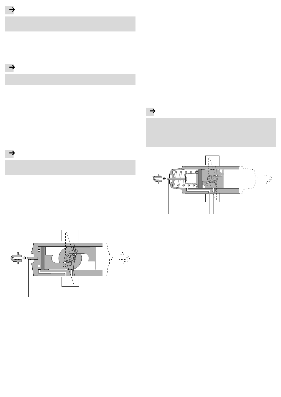
8.2 Adjustment for the DAPS-…-R-… (double-acting) – size 0015 … 1920
For these product variants, the end position that the actuator takes during venting
through port 4 (B) can be adjusted (turn to the right - close process valve).
1
2
3
4
5
1 Lock nut with sealing ring
2 Threaded rod
3 Piston
4 Port 2 (B)
5 Port 4 (A)
Fig. 8
1. Supply compressed air and close the process valve. This fixes the threaded
rods, if necessary – dependent on the current setting. Loosening of the lock nuts
will then not accidentally change the current setting.
2. Screw down the lock nuts with sealing ring on both sides. If the threaded rods
have loosened, retighten them by hand until a light resistance is felt.
3. Supply compressed air and open the process valve. The pistons run into the
inside end position
4. Adjust the end position:
Observe that a complete turn of the threaded rod can change the swivel angle
approx. 1.5° to 3.5° – dependent on the product design.
– Turning threaded rods clockwise reduces the swivel angle.
– Turning threaded rods anti-clockwise increases the swivel angle.
• Turn both threaded rods so they stop the pistons in operation simultaneously.
5. Supply compressed air and close the process valve. The pistons run against the
threaded rods into the outer end position.
6. Check the position of the process valve. To change the swivel angle, repeat
step 3 and 4.
7. If the desired position is found, check whether both threaded rods offer resist-
ance to the pistons in a closed process valve position. If necessary, screw in
loose threaded rods until resistance is felt.
8. Screw the lock nuts back onto the threaded rods – tightening torque 5 Nm.
9. Check the mode of operation of the quarter turn actuator (
section 8.4)
8.3 Adjustment with the DAPS-…-RS.. (single-acting) – size 0015 to 0960
For these product variants, one of the two end positions of the DAPS can be
adjusted – either the end position for right turning or the end position for left
turning.
End position for right turning – closing process valve
Note
For the single-acting DAPS, the end position setting for right turning (closing
process valve) does not have a mechanical stop, since the spring disc is not
mechanically connected to the piston. The threaded rod therefore limits only the
path of the return spring so that the piston comes to rest without spring force.
But the piston movement or turning of the shaft is not mechanically limited and
can be continued through external forces.
1
2
3
4
5
1 Lock nut with sealing ring
2 Threaded rod
3 Piston
4 Port 2 (B)
5 Port 4 (B)
Fig. 9
1. Vent the DAPS and close the process valve. Through spring return, the pistons
run into the inside end position up to the spring disc and are held by the
threaded rods, if necessary. This fixes the threaded rods, if necessary – depend-
ent on the current setting. Loosening of the lock nuts will then not accidentally
change the current setting.
2. Screw down the lock nuts with sealing ring on both sides. If the threaded rods
have loosened, loosen them by hand until a light resistance is felt.
3. Supply compressed air and open the process valve. The pistons move to the
outer end position.
4. Adjust the end position:
Observe that a complete turn of the threaded rod can change the swivel angle
approx. 1.5° to 3.5° – dependent on the product design.
– Turning threaded rods clockwise increases the swivel angle.
– Turning threaded rods anti-clockwise reduces the swivel angle.
• Turn both threaded rods equally far, so that the path of both return springs is
identical.
5. Vent the DAPS and close the process valve. Through spring force, the pistons
are moved into the inside end position until the threaded rods and spring discs
delimit the spring path.
6. Check the position of the process valve. To change the swivel angle, repeat
steps 3 to 6
7. If the desired position is found, check whether both threaded rods offer resist-
ance to the pistons in a closed process valve position. If necessary, screw in
loose threaded rods carefully until resistance is felt.
8. Screw the lock nuts back onto the threaded rods – tightening torque 5 Nm.
9. Check the mode of operation of the quarter turn actuator (
section 8.4)