Feiss F2957-4 User Manual
Lumiere' 4 light chandelier, Installation instructions for, Use minimum 90°c supply conductors
1
Installation Instructions for
Lumiere' 4 Light Chandelier
1.1
F2957-4
Chandelier
F2957/4_
G
P
I
:
ENERAL
RODUCT NFORMATION
This product is listed by one of the following
“ ationally
ecognized
esting aboratory”
N
R
T
L
This product is suitable for dry locations only.
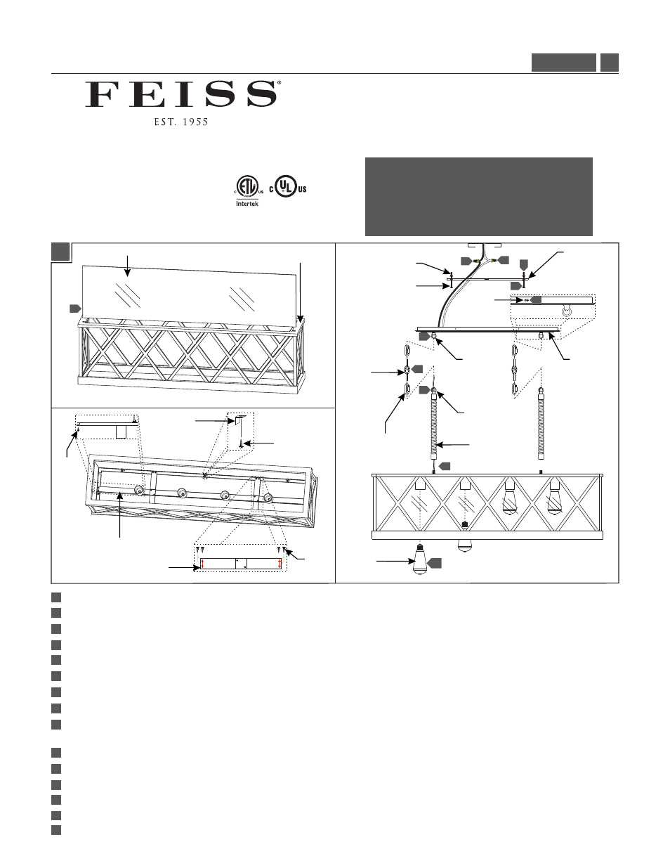
This instruction shows a typical installation.
Align the anchors with the mounting plate holes and install them by pushing them into the ceiling.
Secure the mounting plate to the electrical box with two mounting plate screws provided with electrical box.
Screw the anchor screws into the anchors.
Temporarily remove the socket assembly by removing the sheet screws from the brackets and ends of the socket assembly.
Install the glass panels by carefully sliding them into the frame, then from the inside, secure them using the eight metal sheets and sheet screws.
Reinstall the socket assembly by securing the socket assembly and brackets to the frame using the sheets screws.
Screw the stem to the top of the fixture.
Determine the wanted height of the fixture and remove a portion of the chain by opening a link with pliers.
Install a quick link onto the chain and fixture loop, then install another quick link to the other end of the chain and canopy loop; repeat steps 7-9
for remaining stem and chain.
Weave the cord through the stem, chain, canopy, and out of the electrical box. Trim the cord leaving enough to make electrical connections.
Connect the fixture to a suitable ground in accordance to local electrical codes.
Connect the white fixture wire (square and/or rigid) to the neutral power line wire with a wire nut.
Connect the black fixture wire (round and/or smooth) to the hot power line wire with a wire nut.
Neatly place all the wires into the electrical box, place the canopy onto the mounting plate, and secure it in place by screwing in the fixture screws.
Screw the lamps into the sockets. Refer to the label on the lamp socket for Max Wattage information.
1
2
1A
12
SOCKET
ASSEMBLY
CAUTION - RISK OF FIRE
This product must be installed in accordance with
the applicable installation code by a person familiar
with the construction and operation of the product
and the hazards involved.
Use minimum 90°c supply conductors.
3
4
5
15
MOUNTING
PLATE
STEM
6
7
8
LAMP
9
10
FIXTURE
LOOP
CANOPY
LOOP
13
GLASS PANEL
FRAME
CANOPY
CHAIN
QUICK LINK
ANCHOR
ANCHOR SCREW
3
1
11
12
13
14
METAL
SHEET
SHEET SCREW
SHEET
SCREW
BRACKET
SHEET
SCREW
7
8
9
9
FIXTURE
SCREW
14
5
15