Read process, 2 read process, Manual eks electronic-key adapter serial – EUCHNER Electronic-Key Adapter with serial Interface User Manual
Page 19
Manual EKS Electronic-Key Adapter serial
088796-02-03/05
Subject to technical modifications
Page 19/24
Contents
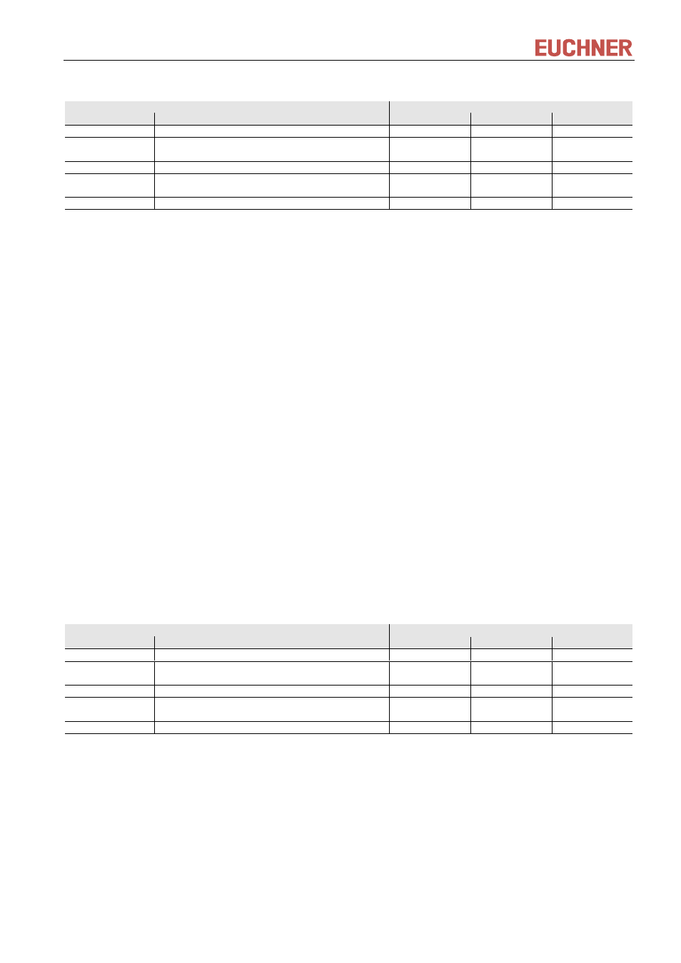
Byte no.
Description
ASCII
hexadecimal
decimal
0
Number of message bytes
07
7
1
2
Command identification
R
F
52
46
82
70
3
Device address
01
1
4
5
Padding data
00
00
0
0
6
Status number
*
Figure 3: Reply message write Electronic-Key read/write - status (message core)
* Status number
00
hex
:
No error
02
hex
:
Electronic-Key not in the operating distance
(For further status numbers see chapter 8.7)
8.4.2 Read process
Command message
(message core, PC/PLC
→ EKS, see Figure 3):
TL (device addr.) (start addr. user data) (number of bytes of user data)
Reply message (message core, EKS
→ PC/PLC, see Figure 5 or Figure 6):
For this command there are two possible replies:
RL (device addr.) (start addr. user data) (number of bytes of user data) (user data)
or
RF (device addr.) (00
hex
,00
hex
) (status number)
The reply message RL (see Figure 5) stands for correct reception of the data.
If an Electronic-Key cannot be read, an RF reply message is received (see Figure 6). The status number then
indicates the cause of the error.
Contents
Byte no.
Description
ASCII
hexadecimal
decimal
0
Number of message bytes
07
7
1
2
Command identification
T
L
54
4C
84
76
3
Device address
01
1
4
5
Start address for the user data
00
00 ... 73
0
0 ... 115
6
Number of bytes of user data
01 ... 74
1 ... 116
Figure 4: Command message read Electronic-Key read/write (message core)