Special features of the serial interface, Communication, Basic message structure – EUCHNER Electronic-Key Adapter with serial Interface User Manual
Page 15: 1 special features of the serial interface, 2 communication, 3 basic message structure, Manual eks electronic-key adapter serial
Manual EKS Electronic-Key Adapter serial
088796-02-03/05
Subject to technical modifications
Page 15/24
8 Operating the Electronic-Key-System using the serial
interface
8.1 Special features of the serial interface
If there is an Electronic-Key within the operating distance of the Electronic-Key adapter, the LED on the front
changes from green to yellow. At the same time the OUT handshake signal (for use as CTS signal) changes
from inactive (0) to active (1). This signal can be used for control purposes to detect whether there is an
Electronic-Key in the Electronic-Key adapter.
8.2 Communication
In this chapter primarily the communication between PC/PLC and the Electronic-Key adapter (referred to as
device in the following tables) is described.
The Electronic-Key adapter is addressed over the serial interface. The commands are given over this serial
interface.
The transfer messages for the commands
Program
(write)
Electronic-Key
Read
Electronic-Key
are based on the transfer protocol 3964R [1]
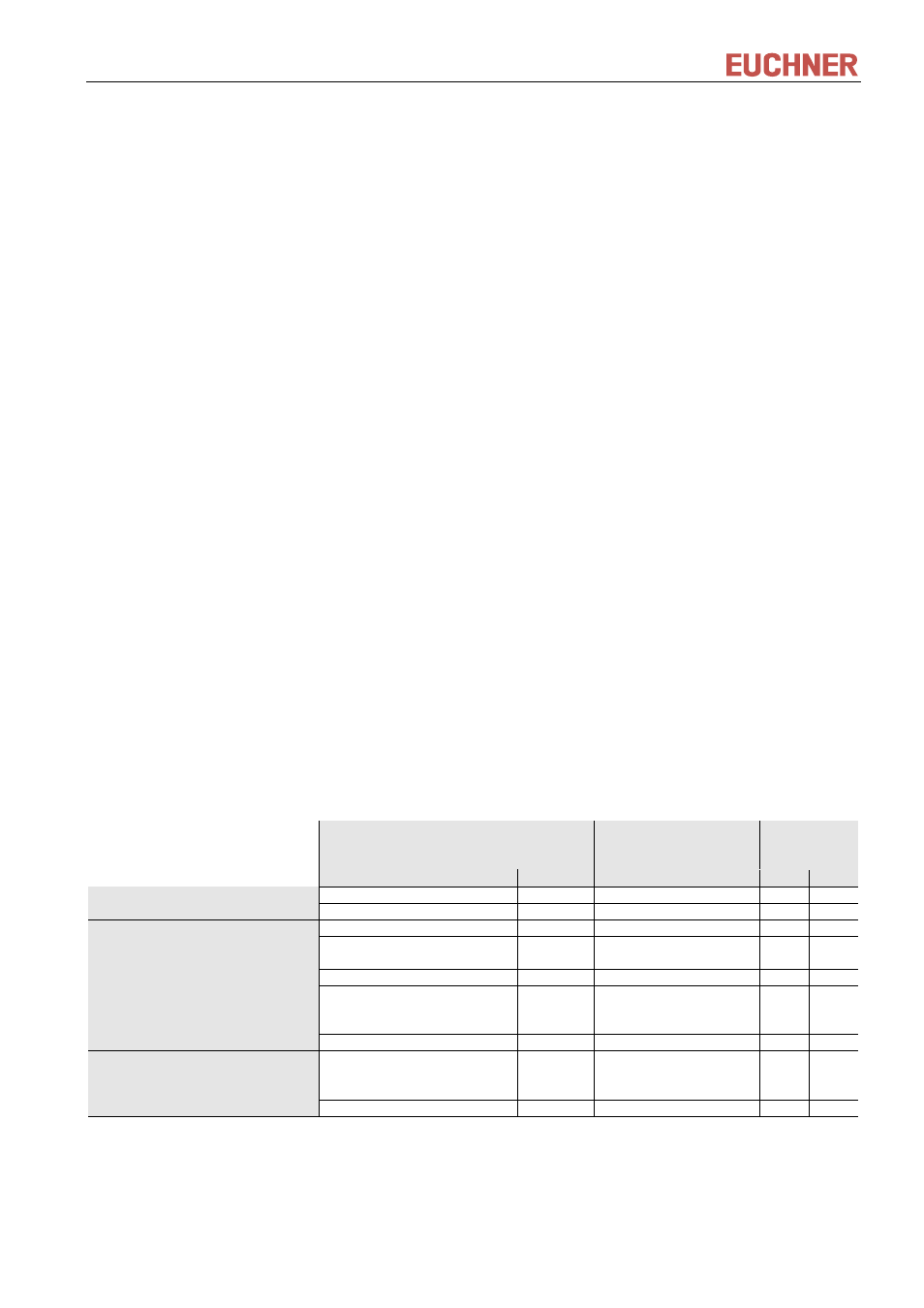
8.3 Basic message structure
Every command and any related data blocks are transferred from and to the Electronic-Key adapter in a
message core within the message frame as per the protocol 3964R (Figure 1: Basic command structure in the
3964R protocol).
In the 3964R protocol, the recipient acknowledges the message received by sending back an acknowledgement
character (DLE). If the acknowledgement is negative (NAK), the complete protocol is repeated. If it is not
possible to correctly transfer the protocol after a total of six attempts, the process is aborted.
Acknowled-
gement from
the recipient
Description
Byte no.
Transmit data in
ASCII format
+
-
3964R procedure start
STX
Connection setup
DLE
NAK
Number of message bytes
0
Command identification
1
2
T or R
command
Device address
3
01
hex
User data description
4
5
6
Start address
Start address
Number of items of data
Message data max. 128 bytes
Message core
User data
7 ... n
3964R procedure termination
DLE
ETX
BCC
Connection termination
DLE
NAK
Figure 1: Basic command structure in the 3964R protocol