Dip switch settings, Out output, Led display – EUCHNER Electronic-Key Adapter with serial Interface User Manual
Page 10: 4 dip switch settings, 5 out output, 6 led display, Manual eks electronic-key adapter serial
Manual EKS Electronic-Key Adapter serial
088796-02-03/05
Subject to technical modifications
Page 10/24
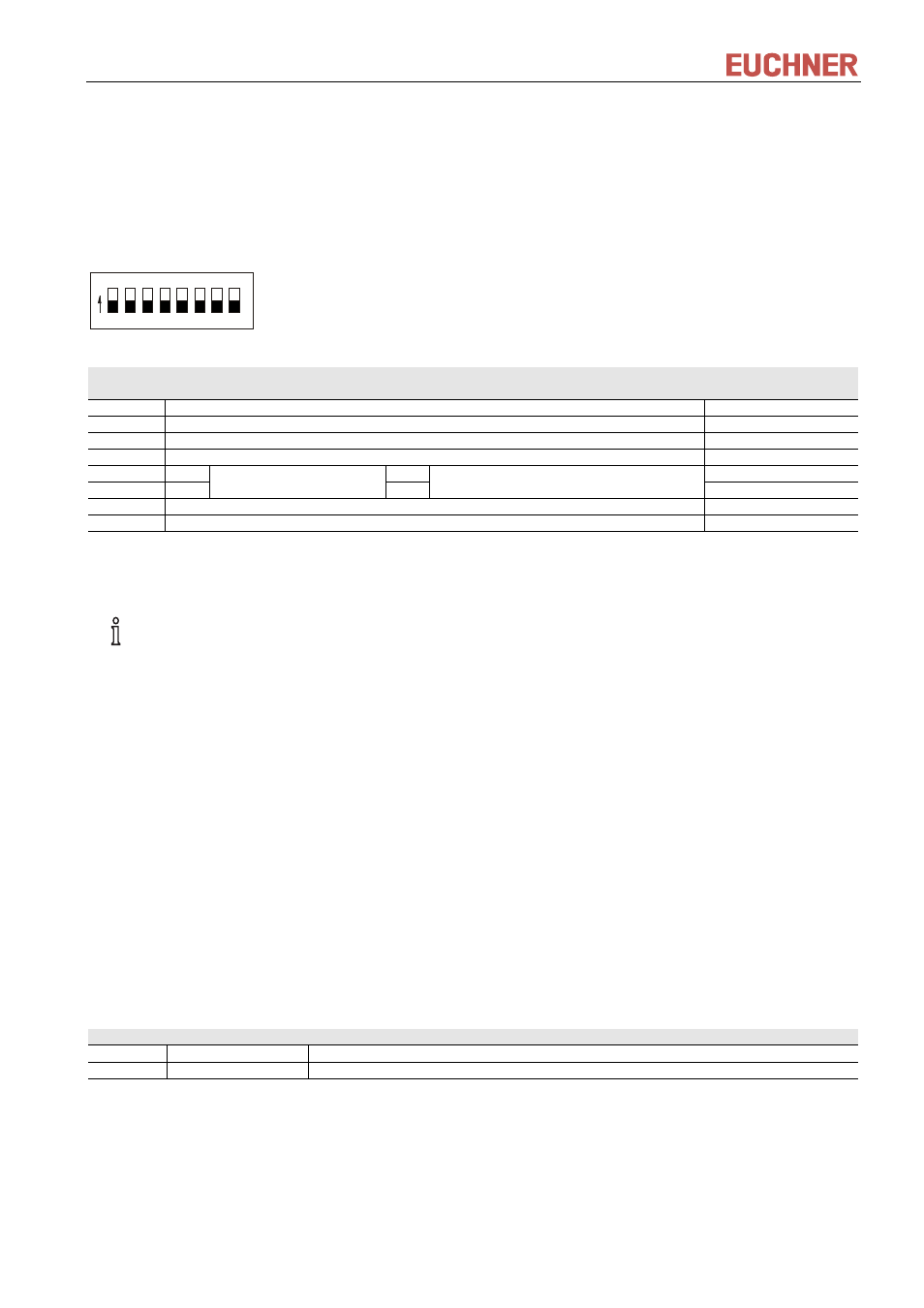
4.4 DIP switch settings
Using the DIP switches S1 to S8, various parameters can be set.
Write protection can be enabled using DIP switch S1. In this way the writing of data to the Electronic-Key
read/write is prevented.
The settings are only applied when the power supply is switched on.
DIP switches, 8-pole:
1 2 3 4 5 6 7 8
ON
DIP
switch
Functions
Factory setting
S8
OFF = Electronic-Key read/write ON = Electronic-Key read-only *
OFF
S7
OFF
S6
OFF
S5
OFF
S4
ON
OFF
ON
S3
ON
RS232
ON
RS422
ON
S2
OFF
S1
ON = write protection for Electronic-Key read/write
OFF
* The read-only transponder type can also be read using the Electronic-Key adapter with serial interface. However, we do
not recommend using this transponder type in new installations.
It is imperative that all DIP switches without a function (S2 and S5 to S7) are set to OFF! In this way
problems with any functions added in the future will be avoided.
4.5 OUT
output
The OUT output signal changes from inactive (0) to active (1) if there is a functional Electronic-Key in the
Electronic-Key adapter. This signal can be used for control purposes to detect whether there is a Electronic-Key
in the Electronic-Key adapter. The function is identical to the "Electronic-Key active" LED display (yellow).
The OUT output is available on the Electronic-Key adapter with two different levels. On pin 8 of the serial
interface socket with RS232 level (for use as CTS signal on the RS232 interface) and on pin 3 of the power
supply screw terminal with a level of DC + 24 V (inactive = 0 V, active = DC + 24 V) for use as a handshake
signal e.g. with a PLC.
4.6 LED
display
The operating statuses of the Electronic-Key adapter are displayed on a 2-color LED on the front.
The illumination of the LED with any color indicates that the operating voltage is present.
Color
Operating status
Description
Green
Ready
Electronic-Key adapter supplied with power and ready.
Yellow
Electronic-Key active There is an Electronic-Key in the Electronic-Key adapter and it has been detected.