Technical data, Figure 3: plungers and approach directions, Figure 4: mounting for safety circuits – EUCHNER GSxxxC1806 12 mm User Manual
Page 4
Operating Instructions Precision Multiple Limit Switches GS...C1806 12 mm
EUCHNER GmbH + Co. KG Kohlhammerstraße 16 D-70771 Leinfelden-Echterdingen Tel. +49/711/75 97-0 Fax +49/711/75 33 16 www.euchner.de [email protected]
Subject to technical modifications; no r
esponsibility is accepted for the accuracy of this information. © EUCHNER GmbH + Co. KG 076850-04-06/11 (translation of the original operating instructions)
±0,
1
1,5
0 -
Ш10
80
6
5
62
28
8
Ш4,8
98
44
8
20
64
120
Ш6,6
13,
5
M25x1,5
12
30
33
46
72
max
.
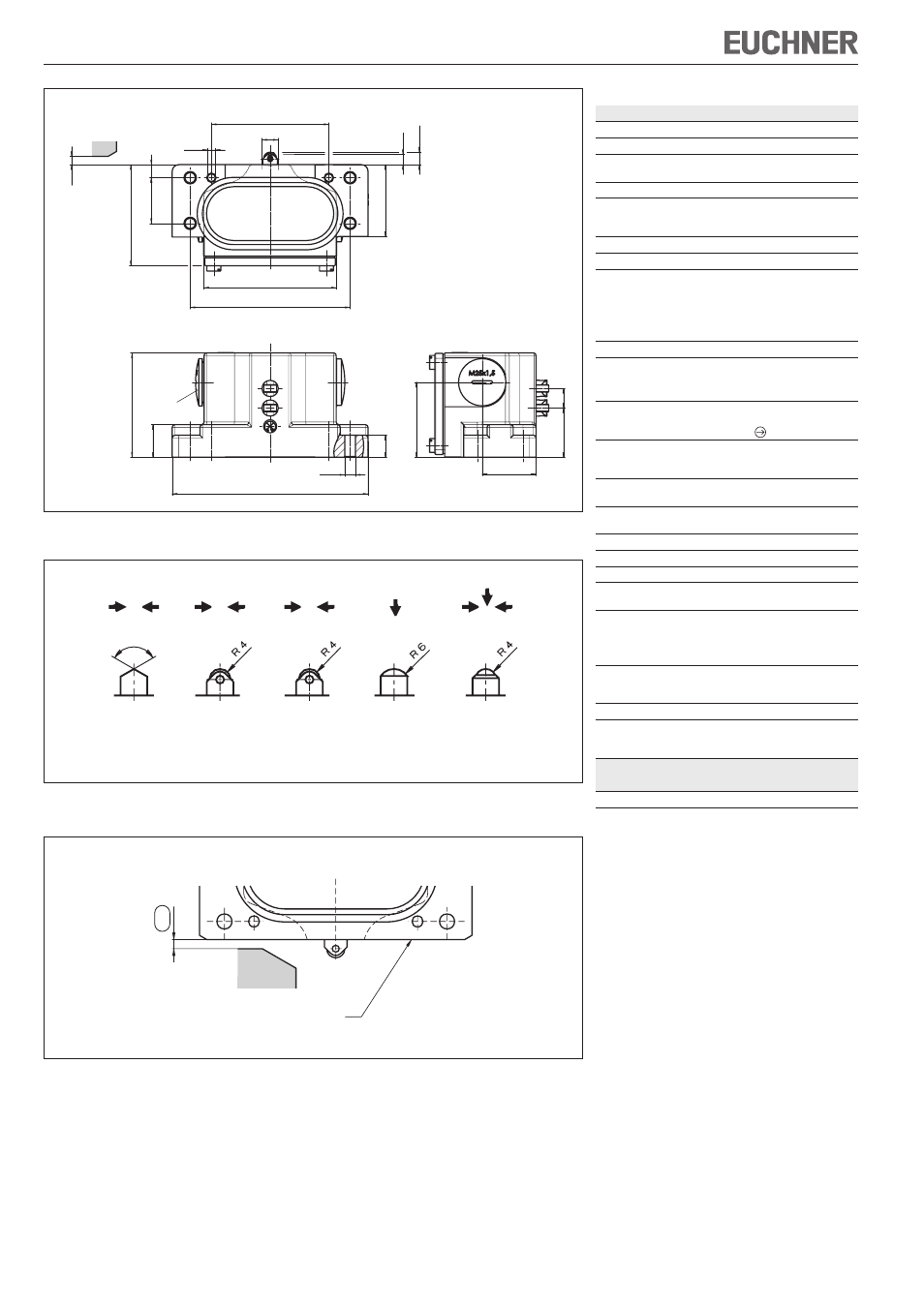
Figure 2: Dimension drawing GS...-502-MC1806
120°
-5°
Figure 3: Plungers and approach directions
Dog
Operating point
Fr
ee position
4
-0
,5
Figure 4: Mounting for safety circuits
Dog
Reference surface
D
Chisel
R
Roller
Slide bearing
B
Roller
Ball bearing
W
Dome
K*
Ball
* only with switching element ES502E
Preferred approach directions
Technical data
Parameter
Value
Housing material
Die-cast aluminum, anodized
Plunger material
Stainless steel
Degree of protection acc. to
IEC 60529
IP 67
Mechanical operating cycles
30 x 10
6
Switching frequency
ES502E
ES508E
300 min
-1
50 min
-1
Ambient temperature
-5 ... +80 °C
Installation position
Any
Approach speed, max.
Plunger
Chisel D
Roller R (slide bearing)
Roller B (ball bearing)
Dome W/ball K
40 m/min
80 m/min
120 m/min
10 m/min
Approach speed, min.
0.01 m/min
Actuating force with switching element
ES502E
ES508E
≥ 20 N
≥ 15 N
Switching element
ES502E
ES508E
1 NO + 1 NC
1 NC
Switching principle
ES502E
ES508E
Snap-action switching contact
Slow-action switching contact
Hysteresis
ES502E
0.8 mm
Contact material
Silver alloy
gold flashed
Connection type
Screw terminals
Conductor cross-section
0.34 ... 1.5 mm
2
Rated insulation voltage
U
i
= 250 V
Rated impulse withstand
voltage
U
imp
= 4 kV
Utilization category switching element according to IEC 60947-5-1
ES502E
ES502E / ES508E
AC-12 250 V 10 A
AC-15 230 V 6 A
DC-13 24 V 6 A
Switching current min.
ES502E
ES508E
10 mA at DC 12 V
10 mA at DC 24 V
Conv. thermal current I
th
10 A
Short circuit protection acc.
to IEC 60269-1
(control circuit fuse)
10 A gG
Reliability figures according to EN ISO 13849-1
for switching element
ES508E
B
10d
2 x 10
7