Operating instructions safety monitors sfm, Controls and indicators, configuration, Service and inspection – EUCHNER SFM-xxx User Manual
Page 4: Technical data
EUCHNER GmbH + Co. KG Kohlhammerstraße 16 D-70771 Leinfelden-Echterdingen Tel. +49 711 7597-0 Fax +49 711 753316 [email protected] www.euchner.de
Operating Instructions Safety Monitors SFM-...
Subject to technical modifications without notice, no liability will be assumed for any detail.
© EUCHNER GmbH + Co. KG
088021
‑06
‑10/13 (translation of par
t of the original operating instructions)
Controls and indicators, configuration
Refer to the safety monitor manual and the configura‑
tion software manual.
Service and inspection
At least once per year, the safety officer must check
for correct operation of the AS‑Interface safety
monitor within the protective system, i.e. for reliable
switch‑off when an associated safety‑related sensor
or switch is triggered.
For this purpose, every safety‑related AS‑Interface
slave must be actuated and the switching behaviour
checked by observing the safety outputs of the AS‑In‑
terface safety monitor (see safety monitor manual).
The safety monitor must be replaced if it malfunc‑
tions or is damaged.
The monitor can be replaced with an equivalent unit
without the need for reconfiguration (see safety
monitor manual).
Liability coverage is voided under the
following conditions
f
if instructions are not followed
f
non‑compliance with safety regulations
f
installation and electrical connection not performed
by authorized personnel
f
non‑implementation of functional checks.
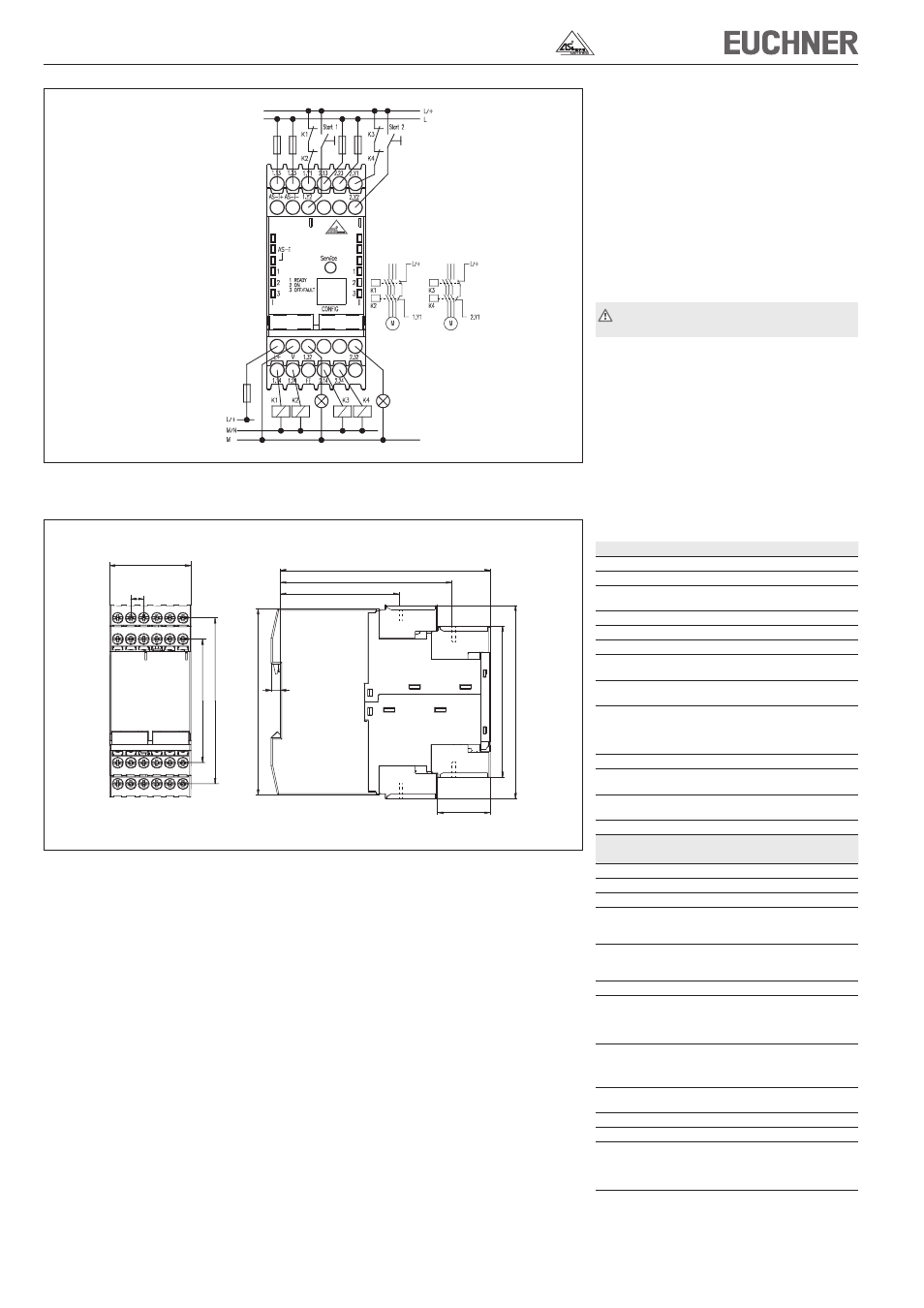
Fig. 7: Dimension drawing safety monitors
45
7,2
2,
86
5,
19
115
94
65
5
28,8
6,
28
9,
50
1
20
1
Fig. 6: Connection safety monitor SFM‑C12
Technical data
Parameter
Value
Housing
Polyamide PA6.6
Dimensions
45 x 105 x 120 mm
Weight
SFM‑...1: approx.350 g
SFM‑...2/SFM‑...2.: approx.450 g
Env. protection to IEC 529
IP 20
Operating temperature
‑20 ... +60 °C
Storage temperature
‑30 ... +70 °C
Assembly
35 mm standard DIN rail
acc. to DIN EN 60715 TH35
EMC protection requirements
acc. to EN 50295
(AS‑Interface standard)
Operating voltage
DC 24 V +15%/‑15%
power supply unit with electrical
separation
(IEC 60742, PELV)
Residual ripple
< 15 %
Rated operating current
SFM‑...1: 150 mA
SFM‑...2/SFM‑...2.: 200 mA
Response time
< 40 ms
< 50 ms for SFM‑B02A
Switch‑on delay
< 10 s
AS-Interface data acc. to
EA code: 7
AS‑Interface Specification 2.1
ID code: F
Total current draw, max.
45 mA
AS‑Interface voltage range
18.5 ... 31.6 V
Inputs
Start
Optocoupler input, high active
Input current approx. 10 mA at
24 V DC
Contactor monitoring
Optocoupler input, high active
Input current approx. 10 mA
at 24 V DC
Outputs
Safety on
Signalling output
PNP transistor output, 200 mA,
protected against short circuit and
polarity reversal
Safety output
SFM‑...1
2 floating NO contact outputs
SFM‑...2/SFM‑...2.
4 floating NO contact outputs
Max. contact load
1 A DC‑13 at 24 V DC
3 A AC‑15 at 230 V AC
Continuous thermal current
3 A per output circuit
External fusing, max.
4 A medium slow‑blow
Overvoltage category
3
for rated operating voltage
300 V AC according to
VDE 0110 Part 1
+AS-i S-