Connecting the cet-ap (general) – EUCHNER CETx-AP-xxx-AH-xxx (Unicode) User Manual
Page 22
Operating Instructions Safety Switch CET.-AP-...-AH-...
22
Connecting the CET-AP (general)
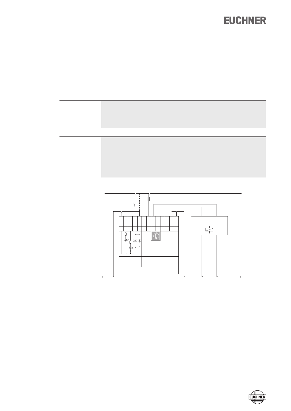
Connect the device as shown in Figure 3. The monitoring output OUT and, if avail-
able, the door monitoring output OUT D can be connected to a control system.
The switches can be reset via the RST input. To do this, a voltage of 24 V is applied
to the RST input for at least 3 seconds. If input RST is not used in your application,
it should be connected to 0 V.
Warning!
In case of an error, loss of the safety function through incorrect connection.
Ì
To ensure safety, both safety outputs (OA and OB) must always be evaluated.
Single-channel use of the safety outputs leads to a loss of the category in
accordance with EN ISO 13849-1.
Important:
The subsystem CET-AP complies with PL e in accordance with EN 13849-1. To
integrate the subsystem in a category 3 or 4 structure, it is necessary to monitor
the downstream load (the feedback loop must be monitored).
These examples show only an excerpt that is relevant for connection of the CET
system. The example illustrated here does not show complete system planning.
The user is responsible for safe integration in the overall system.
Figure 3: Connection example for version with teach-in input and 2 x M12 plug
connectors
GND
DC 24 V
CET-AP
n.c.
1
UB
2
OA
3
OB
4
M12 plug-connector
(8-pin)
OUT
5
n.c.
6
0V UB
7
RST
8
-F1
-F2
0V UCM
1
LED 1
2
LED 2
3
UCM
4
M12 plug-connector
(5-pin)
J
5
Connected
load
Safety
outputs