Mounting, Mounting 8 – EUCHNER CES-I-AR-U-C04 (Unicode) User Manual
Page 8
Operating Instructions Safety Switch CES-I-AR-U-C04
8
Mounting
Caution!
Risk of damage to equipment as a result of incorrect installation. Safety switches
must not be used as a mechanical end stop.
Ì
Fit an additional end stop for the movable part of the safety guard.
Important!
Ì
From the assured switch-off distance S
ar
, the safety outputs are safely shut
down.
Ì
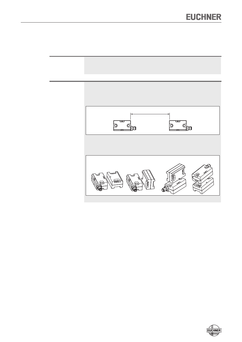
When mounting several safety switches and actuators, observe the stipu-
lated minimum distance to avoid mutual interference.
min. 140 mm
Installation options
Ì
The operating distance changes during the mounting of the actuator as a
function of the material used for the safety guard. Observe direction of arrow
on the device (see figure below).
Permissible approach directions
A
B
C
D
Note the following points:
Ì
Actuator and safety switch must be easily accessible for inspection and re-
placement.
Ì
The switching operation must only be triggered by the specific actuator desig-
nated for this purpose. For permissible combinations please see the table of
possible combinations on page 4.
Ì
Actuator and safety switch must be fitted so that
Ì
the front faces are at the minimum switch-on distance 0.8 x S
ao
or closer
when the safety guard is closed (see section Operating distances). A mini-
mum distance dependent on the actuator and the approach direction must be
maintained for a side approach direction:
- for CES-A-BBN-C04-115271
6 mm (A + B) / 2 mm (C + D)
- for CES-A-BDN-06-104730
10 mm
Ì
when the safety guard is open up to the distance S
ar
(assured switch-off dis-
tance), a hazard is excluded.
Ì
the actuator is positively mounted on the safety guard, e.g. by using the
safety screws included.
Ì
Pay attention to the maximum tightening torque of 0.8 Nm for the safety
switch and actuator mountings.