Connector assignment, safety switch ces-i-ar – EUCHNER CES-I-AR-U-C04 (Unicode) User Manual
Page 13
Operating Instructions Safety Switch CES-I-AR-U-C04
13
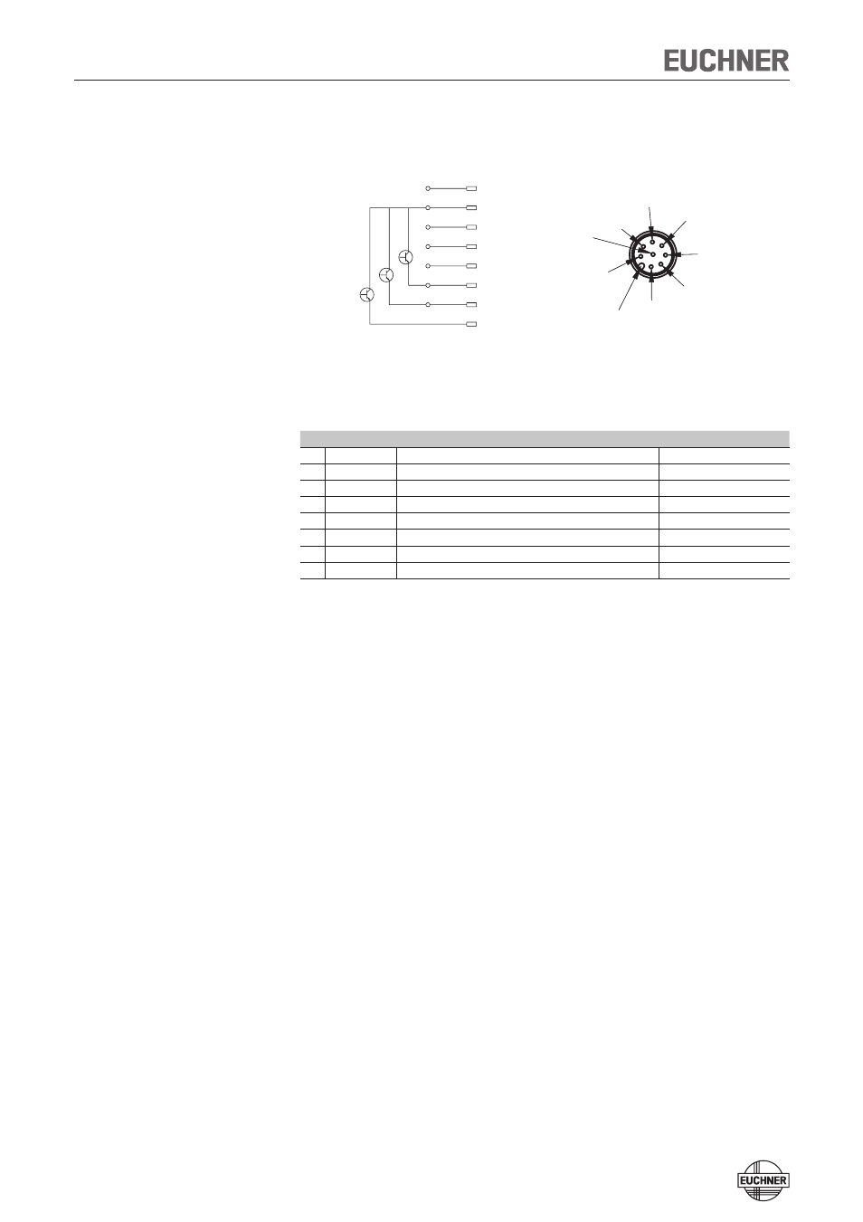
Connector assignment, safety switch CES-I-AR
Figure 2: Connector assignment, safety switch CES-I-AR
Pin Designation
Description
Wire color
1
FI1B
Enable input for channel 2
white
2
UB
Power supply, DC 24 V
brown
3
FO1A
Safety output, channel 1
green
4
FO1B
Safety output, channel 2
yellow
5
OD
Monitoring output
gray
6
FI1A
Enable input for channel 1
pink
7
0V
Ground, DC 0 V
blue
8
RST
Reset input
red
1
7
6
5
4
3
2
8
8
2
7
6
1
3
4
5
UB
0V
FI1A
FI1B
FO1A
FO1B
OD
RST
Coding lug
View on the connection side of the safety switch
See also other documents in the category EUCHNER Safety:
- N1A Single hole fixing limit switch (12 pages)
- NZ Safety switch (12 pages)
- NZ.VZ (15 pages)
- NZ.VZ-xxxVS (16 pages)
- TZxxxAS1 (16 pages)
- TZxxx (20 pages)
- NXxxx (12 pages)
- TXxxx (12 pages)
- SGAxxx (12 pages)
- STAxxx (15 pages)
- STA-TWxxx (Twin) (15 pages)
- NMxxAV/AL (8 pages)
- NMxxWO/RB (12 pages)
- NMxxKB (12 pages)
- NMxxHB (12 pages)
- NMxxAK/AG (8 pages)
- NMxxVZ (15 pages)
- NP (12 pages)
- GPxxx (12 pages)
- TPxxx (12 pages)
- SGPxxx (12 pages)
- SGP-TWxxx (Twin) (12 pages)
- STP-TWxxx (Twin) (15 pages)
- STPxxx (15 pages)
- STP-BIxxx (12 pages)
- STMxxx (12 pages)
- NQxxVZ (8 pages)
- TQxxx (12 pages)
- TKxxx (12 pages)
- ESH (8 pages)
- Hinge ESH Re-adjustable (8 pages)
- MGB-AR (14 pages)
- MGB-L1-xxxARx-xxx (38 pages)
- MGB-L0-xxxARx-xxx (36 pages)
- MGB-LxxB-PNx-xxx (PROFINET) with Data Structure Type B (44 pages)
- MGB-LxxB-PNA-xxx (PROFINET) with Data Structure Type A (36 pages)
- CES-A-ABA-01 (Unicode) (42 pages)
- CES-Axxx (5 pages)
- CES-A-AEA-02B (Unicode) (44 pages)
- CES-A-UBA-01 (Multicode) (40 pages)
- CES-A-UEA-02B (Multicode) (44 pages)
- CES-AZ-ABS-01B (Unicode) (40 pages)
- CES-AZ-UBS-01B (Multicode) (38 pages)
- CES-AZ-AES-xxx (Unicode) (54 pages)
- CES-AZ-UES-xxx (Multicode) (56 pages)