Connection for the read head (m8, 3-pin) – EUCHNER CES-FD-AP-U-01-xxx (Unicode) User Manual
Page 11
Operating Instructions Field Evaluation Unit CES-FD-AP-.-01-…
11
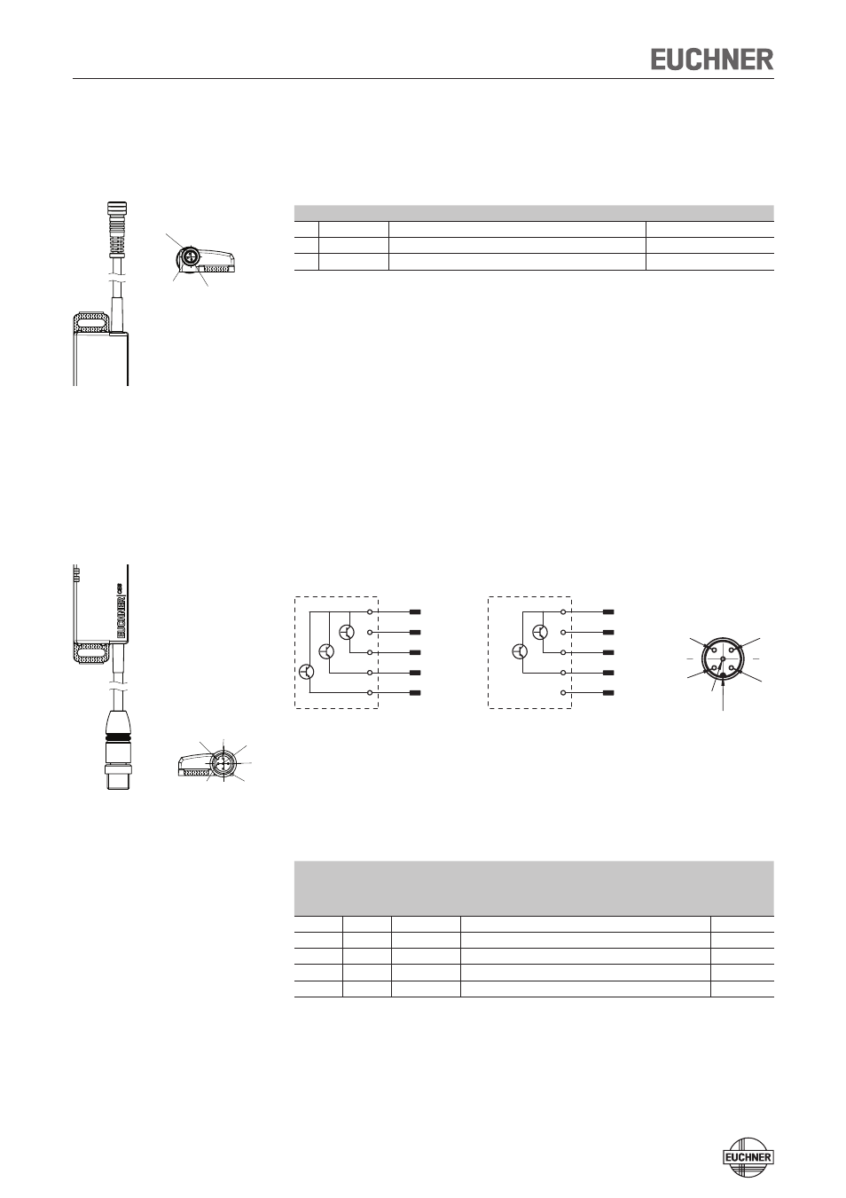
Connector assignment and wire color for field evalu-
ation unit CES-FD-AP-.-01…
Connection for the read head (M8, 3-pin)
Pin Designation
Description
Wire color
1
H1
Data wire
BN
3
H2
Data wire
WH
4
SH
Screen
-
The switch has a permanently connected piece of cable approx. 200 mm long.
With the aid of an extension piece (order. no. 115464) the read head connection
can be extended to max. 700 mm.
Device connection for the field evaluation unit with M12 plug con-
nector, 5-pin
Figure 2: Pin assignment, connection cable for the field evaluation unit with M12
plug connector
Pin
Designation
Description
Wire color
5-pin
5-pin
pin 5
not used
1
1
UB
Power supply, DC 24 V
BN
2
2
FO1A
Safety output, channel 1
WH
3
3
0V
Ground, DC 0 V
BU
4
4
FO1B
Safety output, channel 2
BK
5
-
OD
Monitoring output (optional)
GY
View of connection side on the field evaluation unit
S1.1
S1.3
S1.2
S1.4
S1.5
+UB
0V
FO1A
FO1B
n.c.
4
1
5
2
3
S1.1
S1.3
S1.2
S1.4
S1.5
+UB
0V
FO1A
FO1B
OD
Coding lug
5-pin (optional)
5-pin,
pin 5 not used
M12x1
Stecker X1 / plug connector X1
M8x1
Stecker X2 / plug connector X2
1
4
3
Kodiernase /
coding
1
5
4
3
2
M12x1
Stecker X1 / plug connector X1
M8x1
Stecker X2 / plug connector X2
1
4
3
Kodiernase /
coding
1
5
4
3
2