Inspection and service, Technical data (extract) – EUCHNER MGB-AP User Manual
Page 4
Safety information and Maintenance
(Part of the Operating Instructions for Safety System MGB-AR/MGB-AP)
EUCHNER GmbH + Co. KG Kohlhammerstraße 16 D-70771 Leinfelden-Echterdingen Tel. +49 711 7597-0 Fax +49 711 753316 [email protected] www.euchner.com
Inspection and service
Danger! Loss of the safety function because of dam-
age to the system. In case of damage, the affected
module must be replaced completely. Replacement
of individual parts of a module (e. g. parts of the
evaluation module) is not permitted.
Exception: Pre-assembled replacement lids (available
as spare parts for some MGB versions).
Regular inspection of the following is necessary to
ensure trouble-free long-term operation:
f
Check the switching function
f
Check the secure fastening of the devices and the
connections
f
Check for soiling (e.g. the ventilation slots on the
housing)
Check the safe function of the safety guard par-
ticularly
f
after any setup work
f
each time after the replacement of an MGB module
f
after an extended period without use
f
after every fault
f
after any change to the DIP switch setting
No servicing is required, repairs to the device are only
allowed to be made by the manufacturer.
Technical data (extract)
Parameter
Value
Operating voltage U
B
(reverse polarity protected,
regulated,
residual ripple < 5 %)
24 V DC +10% / -15%
(PELV)
Auxiliary voltage U
A
(reverse polarity protected,
regulated,
residual ripple < 5 %)
24 V DC +10% / -15%
(PELV)
Current consumption I
B
(no load on any outputs)
80 mA
Current consumption with
guard locking solenoid I
A
(with active guard locking and
unloaded outputs O1 ... O4)
350 mA
- Additional current
consumption for version with
controls and indicators in the
cover
max. 20 mA
External fuse
see operating
instructions on CD/DVD
Safety outputs OA/OB
Semiconductor outputs,
p-switching, short circuit-
proof
Output voltage U
OA
/U
OB
1)
HIGH
U
OA
/ U
OB
U
B
-2V ... U
B
LOW
U
OA
/ U
OB
0 ... 1 V DC
Switching current per safety
output
1 ... 200 mA
1) Values at a switching current of 50 mA without taking into ac-
count the cable lengths.
Su
bj
ec
t t
o
te
ch
ni
ca
l m
od
ifi
ca
tio
ns
; n
o
re
sp
on
si
bi
lit
y
is
a
cc
ep
te
d
fo
r t
he
a
cc
ur
ac
y
of
th
is
in
fo
rm
at
io
n.
©
E
UC
HN
ER
G
m
bH
+
C
o.
K
G
11
26
56
-0
3-
06
/1
2
(tr
an
sl
at
io
n
of
p
ar
t o
f t
he
o
rig
in
al
o
pe
ra
tin
g
in
st
ru
ct
io
ns
)
1
2
3
4
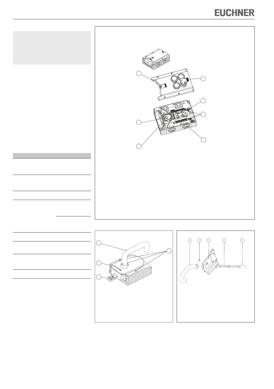
Key:
1
Door handle
2
Locking pins for housing cover and handle
adjustment
3
Lockout bar
4
Bolt tongue
Figure 2: Handle module MGB-H-...
1
2
3
4
5
Figure 3: Escape release MGB-F-... (optional)
Key:
1
Door handle
2
Setscrew
3
Cover
4
Actuation axis, length 110 mm
5
Protective sleeve
1
2
3
5
7
4
6
Key:
1
Cover for mechanical release
2
LED indicator
3
DIP switches
4
Terminals X2 -X5
5
Locking bar
6
Depending on version: Cable entry 20x1.5 or plug connector
7
Auxiliary marking for maximum permitted mounting distance
Note: Depending on the version, additional controls and indicators may be integrated into the cover and
a mounting plate can be included. See enclosed data sheet.
Figure 1: Interlocking/locking module MGB-L.-...