Operating instructions safety switch tk – EUCHNER TKxxx User Manual
Page 4
Operating Instructions Safety Switch TK...
EUCHNER GmbH + Co. KG Kohlhammerstraße 16 D-70771 Leinfelden-Echterdingen Tel. +49/711/75 97-0 Fax +49/711/75 33 16 www.euchner.de [email protected]
Correct use
Safety switches series TK are electromagnetic inter-
lock devices with a guard locking pin.
Safety switches TK do not have protection against
unintentional closing.
In combination with a safety guard and the machine
control, this safety component prevents the safety
guard from being opened while a dangerous machine
movement is being performed.
For this purpose the position of the safety guard must
be monitored with a further safety switch.
For the control system, this means that
starting commands which cause hazardous
situations must become active only when the safety
guard is in protective position and the guard locking
is in locked position.
The locked position of the guard locking must be
released only when the hazardous situation is no
longer present.
Before safety switches are used, a risk assessment
must be performed on the machine in accordance
with
EN ISO 13849-1, Safety of machinery. Safety related
parts of control systems. General principles for
design
EN ISO 14121, Safety of machinery. Risk
assessment. Principles
IEC 62061, Safety of machinery. Functional safety
of safety-related electrical, electronic and
programmable electronic control systems.
Correct use includes compliance with the relevant
requirements for installation and operation, particularly
EN ISO 13849-1, Safety of machinery. Safety related
parts of control systems. General principles for
design
EN 1088, Safety of machinery. Interlocking devices
associated with guards. Principles for design and
selection
EN 60 204-1, Electrical equipment of machines
Important:
The user is responsible for the integration of the
device in a safe overall system. For this purpose
the overall system must be validated, e.g. in
accordance with EN ISO 13849-2.
If the simplified method according to section 6.3
EN ISO 13849-1:2008 is used for validation, the
Performance Level (PL) may be reduced if several
devices are connected one after the other.
If a product data sheet is included with the product,
the information on the data sheet applies in case of
discrepancies with the operating instructions.
Safety precautions
Safety switches fulfill a personal protection function.
Incorrect installation or tampering can lead to severe
injuries to personnel.
Safety components must not be bypassed
(bridging of contacts), turned away, removed or
otherwise rendered ineffective.
On this topic pay attention in particular to the
measures for reducing the possibility of bypassing
from EN 1088:1995+A2:2008, section 5.7.
To achieve safe locking, along with the position
of the guard locking pin, the position of the safety
guard must also be polled (e.g. using an additio-
nal safety switch).
Mounting, electrical connection and setup only
by authorized personnel.
Function
Safety switches series TK permit locking of movable
safety guards.
Version TK1
(guard locking by spring force)
Only switching contacts designated with the
positive opening symbol
are to be used for
the safety circuit.
The guard locking pin is held in the locked position by
spring force and unlocked by electromagnetic
actuation. The spring interlock guard locking functions
in accordance with the closed-circuit current principle.
The safety guard cannot be opened immediately in
the event of interruption of the solenoid power supply.
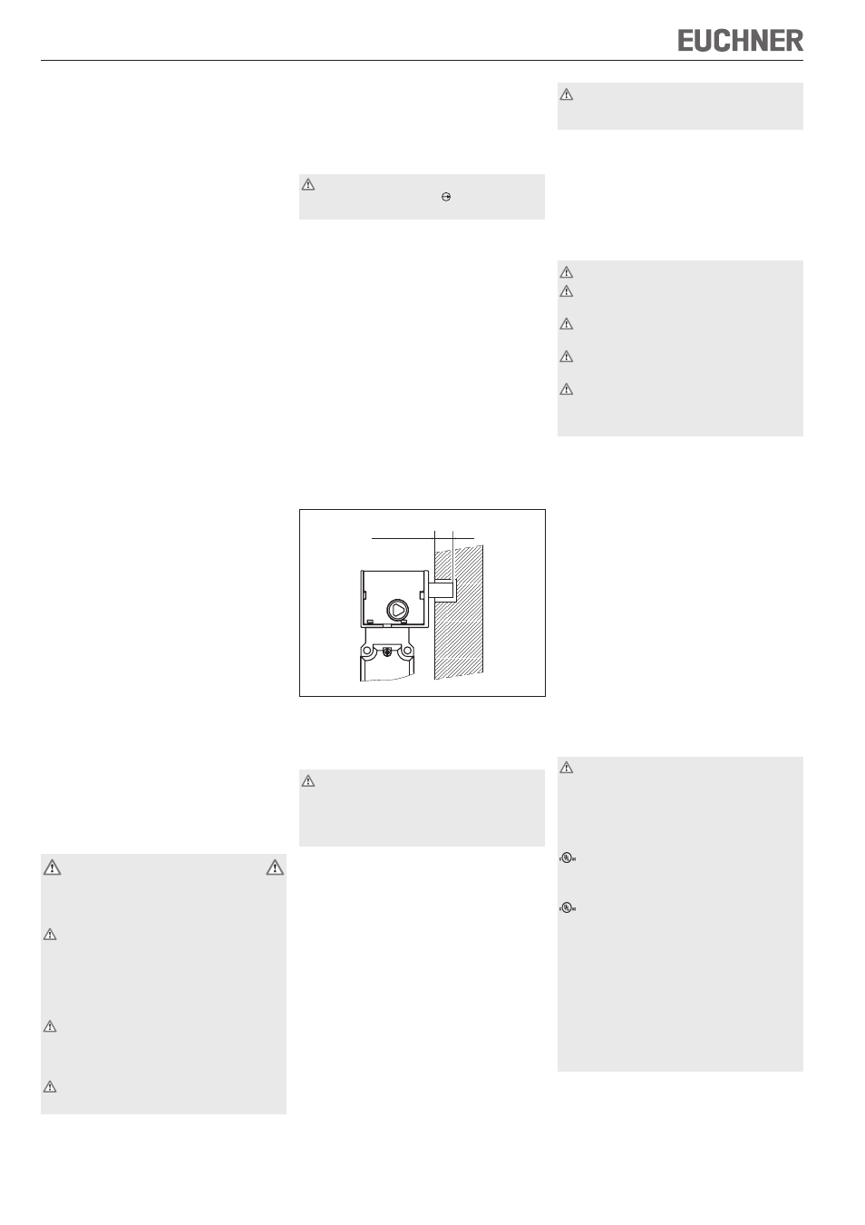
Closing safety guard and activating guard locking
After closing the safety door, the solenoid operating
voltage is removed and the guard locking pin is
extended by spring force. The guard locking is
achieved by the insertion of the guard locking pin,
e. g. in a recess on the door (see Figure 1).
The safety contacts are closed.
Deactivating guard locking, opening safety guard
The guard locking pin is retracted by applying the
solenoid operating voltage and the safety guard can
be opened.
The safety contacts are opened.
Figure 1: Guard locked safety switch TK
Version TK2
(Guard locking by solenoid force)
This type must be used only in special cases
after strict assessment of the accident risk!
The safety guard can be opened immediately in
the event of interruption of the solenoid power
supply!
The guard locking pin is held in the locked position by
electromagnetic force and released by spring force.
The guard locking operates in accordance with the
open-circuit current principle.
Closing safety guard and activating guard locking
After closing the safety door, the solenoid operating
voltage is switched on and the guard locking pin is
extended by the solenoid. The guard locking is
achieved by the insertion of the guard locking pin,
e. g. in a recess on the door (see Figure 1).
The safety contacts are closed.
Deactivating guard locking, opening safety guard
The guard locking pin is retracted by spring force on
the removal of the solenoid operating voltage and
the safety guard can be opened.
The safety contacts are opened.
Only switching contacts designated with the
positive opening symbol are to be used for the
safety circuit.
Mechanical release
In the event of malfunctions, the guard locking can
be released with the mechanical release irrespective
of the state of the solenoid (see Figure 3).
Insert triangular key in the release on the switch
head and turn against the locking direction.
Installation
The locking head is not allowed to be turned.
The guard locking pin must be inserted by at
least 2 mm (see Figure 1).
Safety switches must not be used as an end
stop.
Mount the safety switch only in assembled
condition!
Caution! Risk of burns due to high surface tempera-
ture at ambient temperatures above 40 °C! Protect
switch against touching by personnel or contact
with inflammable material.
Assemble the safety switch so that
access to the switch is difficult for operating
personnel when the safety guard is open.
it is possible to operate the mechanical release and
check and replace the safety switch.
Fit an additional end stop for the movable part of the
safety guard.
Mount the safety switch positively. The switch must
be fastened using four screws (M5) on the switch’s
head. The locking force given only applies to this
type of attachment.
Fit an additional stop for the movable part of the
safety guard.
Protection against environmental influences
A lasting and correct safety function requires that the
actuating head must be protected against the
penetration of foreign bodies such as swarf, sand,
blasting shot etc.
Electrical connection
When choosing the insulation material and wire
for the connections, pay attention to the over-
temperature in the housing (depending on the
operating conditions)!
For TK without plug connector:
For use and applications as per the requirements of
, a rigid copper wire 60/75° is to be used.
For TK with plug connector:
For use and applications as per the requirements of
, a class 2 power supply or a class 2 transformer
according to UL1310 or UL1585 must be used.
Connection cables for safety switches installed at
the place of use must be separated from all moving
and permanently installed cables and un-insulated
active elements of other parts of the system which
operate at a voltage of over 150 V. A constant
clearance of 50.8 mm must be maintained. This does
not apply if the moving cables are equipped with
suitable insulation materials which possess an
identical or higher dielectric strength compared to
the other relevant parts of the system.
The operating voltage for the guard locking
solenoid must match the value on the rating plate
(e.g. U
S
= AC/DC 24 V).
min. 2 mm