Operating instructions safety switch tq, Sk ük – EUCHNER TQxxx User Manual
Page 4
Operating Instructions Safety Switch TQ...
EUCHNER GmbH + Co. KG
Kohlhammerstraße 16
D-70771 Leinfelden-Echterdingen
Tel. +49/711/75 97-0
Fax +49/711/75 33 16
www.euchner.de
Correct use
Safety switches series TQ are electromagnetic interlock
devices with guard locking.
In combination with a safety guard and the machine
control, this safety component prevents the safety guard
from being opened while a dangerous machine movement
is being performed.
For the control system, this means that
starting commands which cause hazardous situations
must become active only when the safety guard is in
protective position and the guard locking is in locked
position.
The locked position of the guard locking must be
released only when the hazardous situation is no longer
present.
Before safety switches are used, a risk assessment must
be performed on the machine in accordance with
EN ISO 13849-1, Safety of machinery. Safety related
parts of control systems. General principles for design
EN ISO 14121, Safety of machinery. Risk assessment.
Principles
IEC 62061, Safety of machinery. Functional safety of
safety-related electrical, electronic and programmable
electronic control systems.
Correct use includes compliance with the relevant
requirements for installation and operation, particularly
EN ISO 13849-1, Safety of machinery. Safety related
parts of control systems. General principles for design
EN 1088, Safety of machinery. Interlocking devices
associated with guards. Principles for design and
selection
EN 60 204-1, Electrical equipment of machines
Important:
The user is responsible for the integration of the device
in a safe overall system. For this purpose the overall
system must be validated, e.g. in accordance with
EN ISO 13849-2.
If the simplified method according to section 6.3
EN ISO 13849-1:2008 is used for validation, the Per-
formance Level (PL) may be reduced if several devices
are connected one after the other.
If a product data sheet is included with the product,
the information on the data sheet applies in case of
discrepancies with the operating instructions.
Safety precautions
Safety switches fulfill a personal protection function.
Incorrect installation or tampering can lead to severe
injuries to personnel.
Safety components must not be bypassed (bridging
of contacts), turned away, removed or otherwise
rendered ineffective.
On this topic pay attention in particular to the measures
for reducing the possibility of bypassing from
EN 1088:1995+A2:2008, section 5.7.
The switching operation may only be triggered by
actuators specially provided for this purpose which
are permanently connected to the protective guard.
Mounting, electrical connection and setup only by
authorized personnel.
Function
The safety switch permits the locking of movable safety
guards.
In the switch head there is a rotating cam that is blocked/
released by the guard locking pin. The guard locking pin
is moved on the insertion / removal of the actuator and
on the activation / deactivation of the guard locking.
During this process the switching contacts are actuated.
If the cam is blocked, the actuator cannot be pulled out
of the switch head guard locking active.
Position monitoring of the safety guard and guard lock
monitoring are performed via two separate switching
elements.
Version TQ1 (guard locking by spring force)
The guard locking pin is held in the locked position by
spring force and released by electromagnetic actuation.
The spring interlock guard locking functions in
accordance with the closed-circuit current principle. The
safety guard cannot be opened immediately in the event
of interruption of the solenoid power supply.
Version TQ2 (guard locking by solenoid force)
This type must be used only in special cases after
strict assessment of the accident risk!
The safety guard can be opened immediately in the
event of interruption of the solenoid power supply!
The guard locking is held in the locked position by an
electromagnetically actuated pin and released by spring
force. The guard locking operates in accordance with
the open-circuit current principle.
Closing safety guard and activating guard locking
The guard locking pin is released by insertion of the
actuator into the safety switch.
TQ1: The guard locking pin is moved to locked position
by spring force.
TQ2: The guard locking pin is moved to locked position
when the solenoid operating voltage is applied.
Door safety circuit SK and monitoring circuit ÜK are
closed.
Deactivating guard locking, opening safety guard
TQ1: The guard locking pin releases the cam when the
solenoid operating voltage is applied.
The monitoring circuit is opened.
The actuator can be removed.
Safety circuit SK is positively opened and blocked in this
position when the actuator is removed. This signals that
the safety guard is open.
TQ2: The guard locking pin releases the cam when the
solenoid operating voltage is switched off.
The monitoring circuit is opened.
The actuator can be removed.
Safety circuit SK is positively opened and blocked in this
position when the actuator is removed. This signals that
the safety guard is open.
Mechanical release
In case of malfunctions, the guard locking can be
deactivated using the mechanical release (see Figure 1
and 2).
Mechanical release with triangular key
Always turn triangular key to the related stop!
If the key is not turned to the stop, incorrect
switching or even damage to the safety switch may
result.
Fig. 1: Mechanical release with triangular key
Insert triangular key in the release on the switch and
turn 90° to the released position.
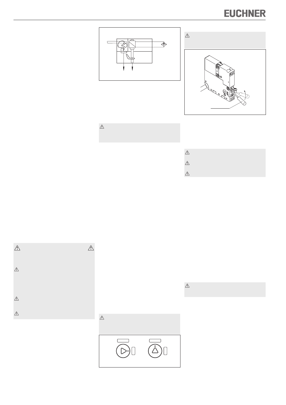
Mechanical release with screwdriver
Only use in an emergency!
After release the screw must be tightened to 0.3 to
max. 0.5 Nm.
Fig. 2: Mechanical release with screwdriver
Remove screw on the side of the safety switch (under
the actuating slot).
Using a small screwdriver, press the tongue inside in
the direction of the LED until the actuator is released.
Mounting
The switch must be protected against contact with
inflammable material or accidental touching.
Safety switches and actuators must not be used as
an end stop.
Mount the safety switch only in assembled condition!
Assemble the safety switch so that
access to the switch is difficult for operating personnel
when the safety guard is open
operation of the mechanical release is still possible
inspection and replacement by authorized personnel
is possible.
Insert the actuator in the actuating head.
Mount the safety switch positively.
Permanently connect the actuator to the safety guard
using rivets or by welding.
Fit an additional stop for the movable part of the safety
guard.
Protection against environmental influences
A lasting and correct safety function requires that the
actuating head must be protected against the penetration
of foreign bodies such as swarf, sand, blasting shot etc.
Cover the actuating slot, the actuator and the rating plate
during painting work!
Electrical connection
When choosing the insulation material, attention is
to be paid to the over-temperature in the housing
(depending on the operating conditions).
The operating voltage for the guard locking solenoid must
match the value on the rating plate (e.g. U
S
= DC 24 V).
SK ÜK
E1
E2
Solenoid
Safety guard closed,
actuator locked
UNLOCK
LOCK
UNLOCK
LOCK
Locked
Unlocked
Screwdriver