Operating instructions safety switch np, Correct use, Safety precautions – EUCHNER NP User Manual
Page 4: Function, Mounting, Changing the actuating direction, Mounting the adapter np-k, Protection against environmental influences, Switching elements and switching functions, Electrical connection
Operating Instructions Safety Switch NP
Correct use
Safety switches series NP are interlocking devices
without guard locking.
In combination with a separating safety guard, this
safety component prevents the safety guard from
being opened while a dangerous machine movement
is being performed. A stop command is triggered if
the safety guard is opened during the dangerous
machine function.
The safety switches series NP comply with the
regulations of EN 60947-5-1 (incl. Annex K) and
comply with the requirements of the employers’ liability
insurance associations for machines, installations and
personnel protection.
Before safety switches are used, a risk assessment
must be performed on the machine in accordance
with
EN ISO 13849-1, Safety of machinery. Safety related
parts of control systems. General principles for
design
EN ISO 14121, Safety of machinery. Risk
assessment. Principles
IEC 62061, Safety of machinery. Functional safety
of safety-related electrical, electronic and
programmable electronic control systems.
Correct use includes compliance with the relevant
requirements for installation and operation, particularly
EN ISO 13849-1, Safety of machinery. Safety related
parts of control systems. General principles for
design
EN 1088, Safety of machinery. Interlocking devices
associated with guards. Principles for design and
selection
EN 60 204-1, Electrical equipment of machines
Important:
The user is responsible for the integration of the
device in a safe overall system. For this purpose
the overall system must be validated, e.g. in
accordance with EN ISO 13849-2.
If the simplified method according to section 6.3
EN ISO 13849-1:2008 is used for validation, the
Performance Level (PL) may be reduced if several
devices are connected one after the other.
If a product data sheet is included with the product,
the information on the data sheet applies in case of
discrepancies with the operating instructions.
Safety precautions
Safety switches fulfill a personal protection function.
Incorrect installation or tampering can lead to severe
injuries to personnel.
Safety components must not be bypassed
(bridging of contacts), turned away, removed or
otherwise rendered ineffective.
On this topic pay attention in particular to the
measures for reducing the possibility of bypassing
from EN 1088:1995+A2:2008, section 5.7.
The switching operation may only be triggered
by actuators specially provided for this purpose
which are permanently connected to the
protective guard.
Mounting, electrical connection and setup only
by authorized personnel.
Function
The safety switch signals that the safety guard is
closed.
The switch does not perform guard locking!
Closing
The safety contacts are closed by inserting the
actuator.
Opening
The safety contacts are positively opened by
withdrawing the actuator.
Mounting
Safety switches and actuators must not be used
as an end stop.
Mount the safety switch only in assembled
condition!
Assemble the safety switch so that
access to the switch is difficult for operating
personnel when the safety guard is open.
inspection and replacement by authorized personnel
is possible.
Insert the actuator in the actuating head.
Mount the safety switch positively.
Permanently connect the actuator to the safety
guard so that it cannot be detached, e.g. using the
enclosed non-removable screws, rivets or welding.
Fit an additional stop for the movable part of the
safety guard.
Changing the actuating direction
Increased overtravel of the actuator with a
vertical approach direction is only possible with
the adapter NP-K.
Fig. 1: Changing the actuating direction
Remove the screws from the actuating head.
Set the required direction.
Tighten the screws with a torque of 0.6 Nm.
Cover the unused actuating slots with the enclosed
slot covers.
Mounting the adapter NP-K
Fig. 2: Mounting the adapter NP-K
Remove the screws from the actuating head.
Fit extension (1) to the plunger.
Fit spacer (2) to the switch.
Mount actuating head in the required direction using
screws enclosed (3).
Protection against environmental influences
A lasting and correct safety function requires that the
actuating head must be protected against the
penetration of foreign bodies such as swarf, sand,
blasting shot, etc.
Cover the actuating slot, the actuator and the rating
plate during painting work!
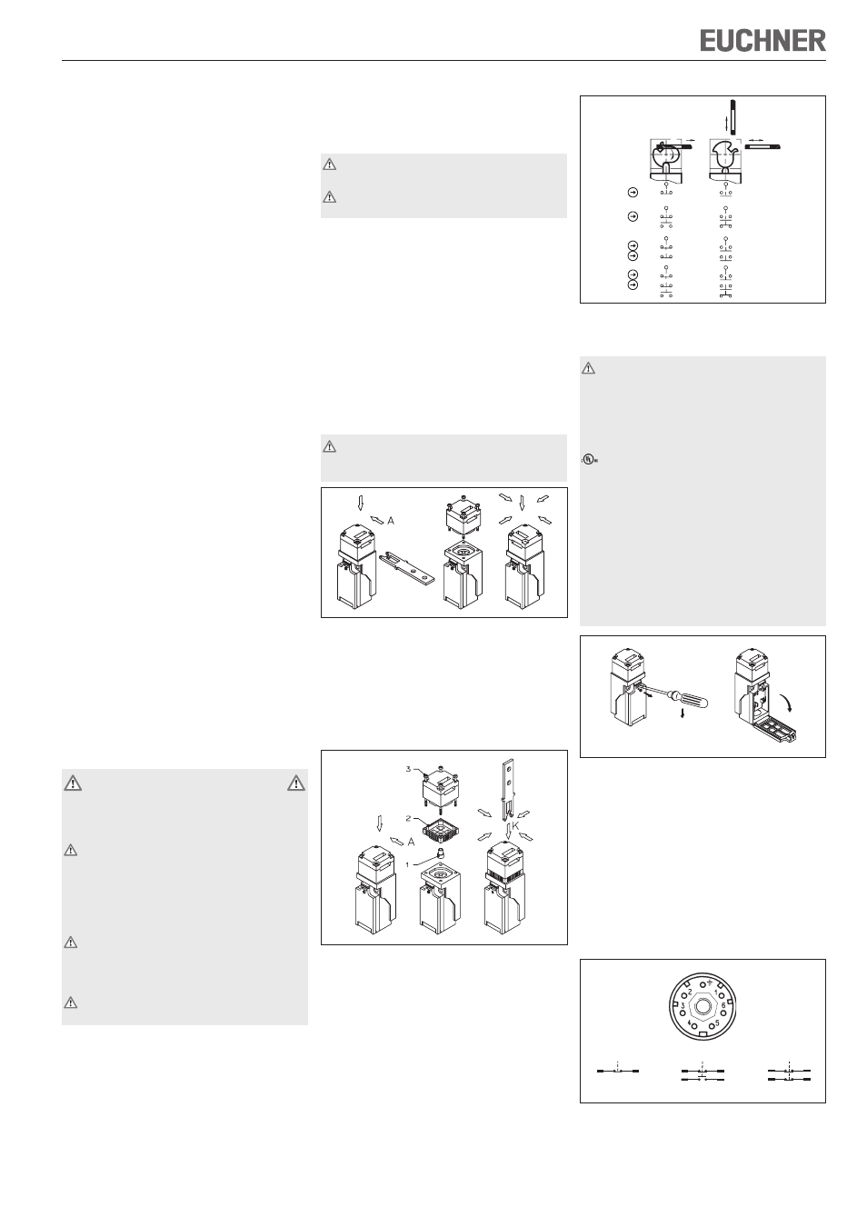
Switching elements and switching functions
Fig. 3: Switching elements and switching functions
Electrical connection
When choosing the insulation material and wire
for the connections, pay attention to the over-
temperature in the housing (depending on the
operating conditions)!
For NP with plug connector:
For use and applications as per the requirements of
, a class 2 power supply or a class 2 transformer
according to UL1310 or UL1585 must be used.
Connection cables for safety switches installed at
the place of use must be separated from all moving
and permanently installed cables and un-insulated
active elements of other parts of the system which
operate at a voltage of over 150 V. A constant
clearance of 50.8 mm must be maintained. This does
not apply if the moving cables are equipped with
suitable insulation materials which possess an
identical or higher dielectric strength compared to
the other relevant parts of the system.
Fig. 4: Opening the safety switch
Version NP1... (cable entry)
Fit cable gland M20 x 1.5 with appropriate degree
of protection.
Conductor cross-section 0.5 to 1.5 mm².
For terminal assignment see Figure 3.
Tighten the screws with a torque of 0.5 Nm.
Check that the cable entry is sealed.
Close the cover and screw in position.
Version NP2... (plug connector)
Conductor cross-section 0.5 to 1.5 mm².
Fig. 5: Plug connector terminal assignment
View
connection side
21
22
13
14
22
21
618
628
2
1
4
3
2
1
11
12
22
21
638
2
1
4
3
Door
open
Door
closed
618
628
638
v
h
21
22
21
22
21
22
21
22
21
22
21
22
13
14
13
14
11
12
11
12
648
31
32
31
32
21
22
21
22
13
14
13
14