Operating instructions safety switches nx – EUCHNER NXxxx User Manual
Page 4
Operating Instructions Safety Switches NX...
Correct Use
Safety switches series NX are interlocking devices
without guard locking.
In combination with a separating safety guard, this
safety component prevents dangerous machine
movements from being performed for as long as the
safety guard is open. A stop command is triggered
if the safety guard is opened during the dangerous
machine function.
The safety switches series NX comply with the regu-
lations of EN 60947-5-1 (incl. Annex K) and comply
with the requirements of the employers' liability
insurance associations for machines, installations
and personnel protection.
Before safety switches are used, a risk assessment
must be performed on the machine in accordance
with
EN ISO 13849-1, Safety of machinery. Safety re-
lated parts of control systems. General principles
for design
EN ISO 14121, Safety of machinery. Risk assess-
ment. Principles.
IEC 62061, Safety of machinery – Functional
safety of safety-related electrical, electronic and
programmable electronic control systems.
Correct use includes compliance with the relevant
requirements for installation and operation, in
particular
EN ISO 13849-1, Safety of machinery. Safety re-
lated parts of control systems. General principles
for design
EN 1088, Safety of machinery. Interlocking
devices associated with guards. Principles for
design and selection
EN 60204-1, Safety of machinery. Electrical equip-
ment of machines. General requirements.
Important:
The user is responsible for safe integration of the
device in a safe overall system. For this purpose
the overall system must be validated, e.g. in ac-
cordance with EN ISO 13849-2.
If the simplified method according to section 6.3
EN ISO 13849-1:2008 is used for validation, the
Performance Level (PL) may be reduced if several
devices are connected one after the other.
If a product data sheet is included with the product,
the information on the data sheet applies in case of
discrepancies with the operating instructions.
Safety Precautions
Safety switches perform a personal protection
function. Incorrect installation or tampering can
lead to severe injuries to personnel.
Safety components must not be bypassed
(bridging of contacts), turned away, removed
or otherwise rendered ineffective.
On this topic pay attention in particular to the
measures for reducing the possibility of bypassing
according to EN 1088:1995.A2:2008, sec. 5.7.
The switching operation may only be triggered
by actuators specially provided for this pur-
pose which are permanently connected to the
protective guard.
Mounting, electrical connection and setup only
by authorized personnel.
Function
The safety switch signals that the safety guard is
closed.
The switch does not perform guard locking!
Closing
The safety contacts are closed by inserting the
actuator.
Opening
The safety contacts are positively opened by with-
drawing the actuator.
Installation
Safety switches and actuators must not be used
as an end stop.
Mount the safety switch only in assembled
condition!
Assemble the safety switch so that
access to the switch is difficult for operating per-
sonnel when the safety guard is open.
address programming, inspection and replace-
ment by authorized personnel are possible.
Insert the actuator in the actuating head.
Mount the safety switch positively.
Permanently connect the actuator to the safety
guard so that it cannot be detached, e.g. using
the enclosed non-removable screws, rivets or
welding.
Fit an additional end stop for the movable part of
the safety guard.
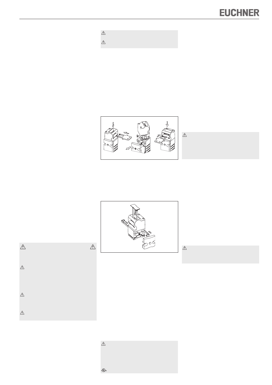
Changing the Actuating Direction
Figure 1: Changing the actuating direction
Unscrew and open switch cover.
Remove actuating head from the switch by turn-
ing and refit in the required position (bayonet
fastening).
Fit locking pins for protection against twisting
(Figure 2). It is then not possible to change the
actuating direction again.
Figure 2: Fitting the locking pins and the slot cover
Close the cover and screw in position.
Cover the unused actuating slot with the enclosed
slot covers (Figure 2).
Protection Against Environmental Influ-
ences
A lasting and correct safety function requires that
the actuating head must be protected against the
penetration of foreign bodies such as swarf, sand,
blasting shot, etc.
Cover the unused actuating slot with the slot
cover.
Cover the actuating slot, the actuator and the rating
plate during painting work!
Only use solvent-free cleaning agents to clean the
switch!
Electrical Connection
When choosing the insulation material and wire
for the connections, pay attention to the over-
temperature in the housing (depending on the
operating conditions)!
For NX without plug connector:
For use and applications as per the requirements of
, copper wire 60/75 °C is to be used.
Version NX1... (cable entry M20x1.5/NPT ½",
see rating plate)
Unscrew locking screw for the required insertion
opening.
Fit cable gland M20x1.5 or NPT½".
Important: To achieve the specified degree of
protection, use a cable gland from EUCHNER (order.
no. 110 132, 110 133 or 110 134).
Conductor cross-section from 0.34 mm² to max.
1.5 mm².
For pin assignment see Figure 3.
Tighten the screws with a torque of 0.6 Nm.
Check that the cable entry is sealed.
Close the cover and screw in position.
Optional LED module L024
Max. outer diameter that can be connected
1.0 mm.
For pin assignment see Figure 4.
Due to the restricted space for wiring, use wires
as thin as possible (recommendation 0.25 mm²)!
Observe current rating of the wire!
Functional Check
Warning! Danger of fatal injury as a result of
faults in installation and functional check.
Before carrying out the functional check, make
sure that there are no persons in the danger
area. Observe the valid accident prevention
regulations.
After installation and any fault, the safety function
must be fully checked. Proceed as follows:
Mechanical function test
The actuator must slide easily into the actuating
head. Close the safety guard several times to check
the function.
Electrical function test
1. Switch on operating voltage.
2. Close all safety guards.
The machine must not start automatically.
3. Enable operation in the control system.
4. Open the safety guard.
The machine must switch off and it must not be
possible to start it as long as the safety guard
is open.
Repeat steps 2 - 4 for each safety guard.
Inspection and Service
If damage or wear is found, the complete switch
and actuator assembly must be replaced.
Replacement of individual parts or assemblies
is not permitted!
No servicing is required, but regular inspection
of the following is necessary to ensure trouble-free
long-term operation:
correct switching function
secure mounting of components
dirt and wear
sealing of cable entry
loose cable connections or plug connectors.
Note:The year of manufacture can be seen in the
bottom, right corner of the rating plate.
Exclusion of Liability under the Following
Conditions:
incorrect use
non-compliance with safety regulations
installation and electrical connection not per-
formed by authorized personnel
failure to perform functional checks.
A