Attach faceplate, Unison heritage series – ETC Unison Heritage Fader Station User Manual
Page 4
E T C I n s t a l l a t i o n G u i d e
Unison Heritage Series
Unison Heritage Fader Station
Page 4 of 4
Electronic Theatre Controls, Inc.
Step 4:
If required for the station type, install button caps so that the clear
light tunnels protrude through the caps. Button caps are supplied
with the faceplate kit.
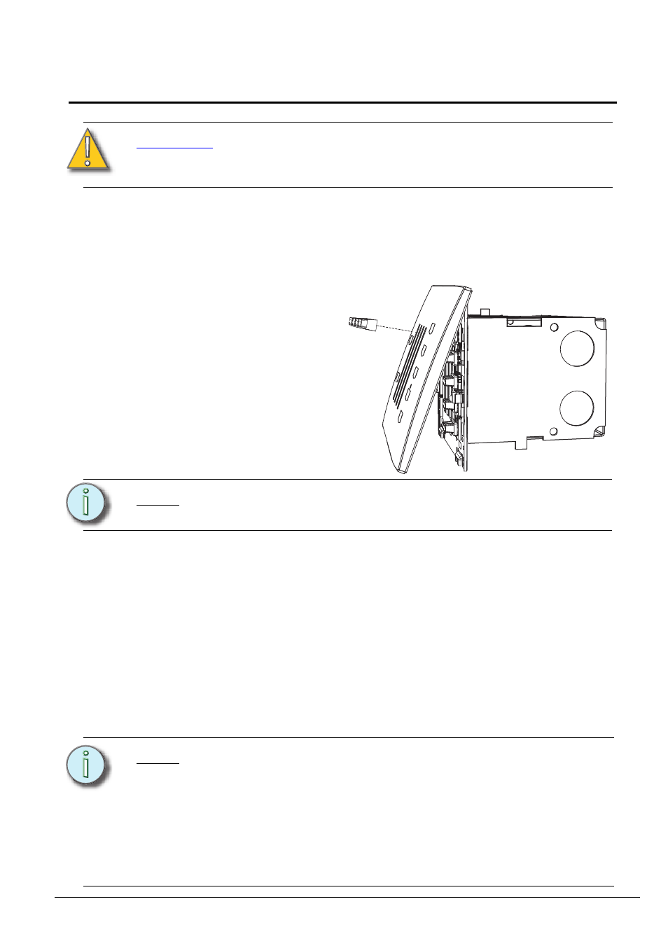
Attach Faceplate
Step 1:
Align the top of the faceplate approximately 20 degrees from the
station.
Step 2:
Hook the top of the faceplate to the tabs located on the station
electronics assembly. To ensure the faceplate is hooked properly on
the top hook, wiggle it slightly side to side while the bottom is angled
about 20 degrees from the wall.
Step 3:
Swing the bottom of the faceplate down until the magnets engage.
Step 4:
If the faceplate does not fully attach automatically, wiggle the bottom
of the plate until the magnets are seated properly to the station and
the faceplate is secure.
Step 5:
Install fader knobs to the sliders.
C A U T I O N :
To improve successful station and wall plate installation, do
not over tighten the screws. If screws are over tightened,
button activation can be negatively impacted.
N o t e :
Button caps are installed before the faceplate is attached.
Reference Step 4 of the previous procedure.
N o t e :
The Paradigm Architectural Control Processor to which this
Heritage station is connected must learn, or be told, the station
hardware address (a.k.a. neuron ID). This ID can be manually
entered into the configuration (as labeled on the station metal)
using LightDesigner software, or can be identified by the
connected Paradigm ACP using the "Connect a Device" menu.
Reference the Unison Paradigm Architectural Control
Processor Configuration Manual; specifically the section on
Arch Setup Menu, LonWorks Connections.
The faceplate is secured to the
station with two magnets that
are located on the bottom side
of the faceplate. The faceplate
kit includes all buttons and
fader knobs required.