ETC Unison Heritage Contact and Fader Interface User Manual
E t c, Unison, Heritage contact and fader interface
E T C
®
I n s t a l l a t i o n G u i d e
Unison
®
Heritage Contact and Fader Interface
Unison
®
Heritage Contact and Fader Interface
Page 1 of 4
Electronic Theatre Controls, Inc.
Corporate Headquarters
3031 Pleasant View Road, P.O. Box 620979, Middleton, Wisconsin 53562-0979 USA
Tel +608 831 4116
Fax +608 836 1736
London, UK
Unit 26-28, Victoria Industrial Estate, Victoria Road, London W3 6UU, UK
Tel +44 (0)20 8896 1000
Fax +44 (0)20 8896 2000
Rome, IT
Via Ennio Quirino Visconti, 11, 00193 Rome, Italy
Tel +39 (06) 32 111 683
Fax +44 (0) 20 8752 8486
Holzkirchen, DE
Ohmstrasse 3, 83607 Holzkirchen, Germany
Tel +49 (80 24) 47 00-0
Fax +49 (80 24) 47 00-3 00
Hong Kong
Rm 1801, 18/F, Tower 1 Phase 1, Enterprise Square, 9 Sheung Yuet Road, Kowloon Bay, Kowloon, Hong Kong
Tel +852 2799 1220
Fax +852 2799 9325
Service: (Americas)
(UK)
(DE)
(Asia)
Web:
Copyright © 2008 ETC. All Rights Reserved.
Product information and specifications subject to change.
7181M2110
Rev A
Released 10/2008
Overview
This guide includes instruction for installation of the Unison Heritage Contact Interface and Unison
Heritage Fader Interface.
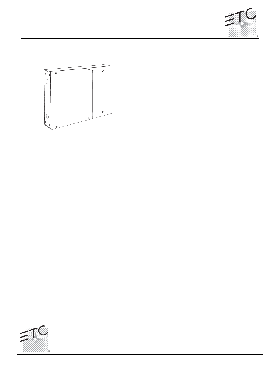
The Unison Heritage Contact Interface (model# UHCI) provides
convenient interface and integration to external devices by sending
and receiving contact closures. The interface enclosure provides
up to eight switch input and relay output connections. Closures are
configurable for either maintained or momentary operation.
The Unison Heritage Fader Interface (model# UHFI) provides
interface to external devices, such as faders or sensors, through a
variable 0-3.3 Vdc analog signal. The interface enclosure consists
of eight fader input connections and eight output lamp-driver
connections.
Product Specification
Installation Requirements
• Surface mount using the mounting keyholes provided.
• Thermal requirements
•
Ambient room temperature of 0-40°C (32-104°F) with an ambient humidity of 30-90%, non-
condensing.
• Wiring requirements:
•
Connect to the Echelon
®
LinkPower
®
(LinkConnect) control network utilizing low voltage
Class II wiring. Wiring is topology free and polarity independent over Belden 8471 (or
approved equal).
•
Connect two 16 AWG (1.5mm
2
) wires for 24 Vdc Auxiliary Power.
•
Connect one 18-10 AWG (0.75-6mm
2
) ESD drain (ground) wire.
•
Switch terminals accept 18-10 AWG (0.75-6mm
2
).
Contact Interface
• Dry contact inputs with no voltage applied.
• Dry contact outputs consist of Normally-Open (NO) 2 pole contact closure outputs, rated up to 1
amp at 28 Vdc, .5A at 120 VAC.
•
Relay outputs are capable of switching up to eight resistive or inductive loads.
• Inputs and outputs are configurable in the Paradigm configuration using LightDesigner software.
• Contact inputs support up to 1,000 feet (305m) of 16 AWG (1.5mm
2
) wire between input and
common.
Fader Interface
• Enclosure provides eight fader input connections and to eight lamp-driver outputs.
• Fader supply voltage is +3.3 Vdc. Each fader input requires signal between 3.3 Vdc and 0 Vdc.
• Each lamp driver output provides 100mA at 24 Vdc.
• Lamp outputs support 1,000 feet (305m) of 16 AWG (1.5mm
2
) wire.