Connecting the wiring, Unison heritage series – ETC Unison Heritage Button Station User Manual
Page 2
E T C I n s t a l l a t i o n G u i d e
Unison Heritage Series
Unison Heritage Button Station
Page 2 of 4
Electronic Theatre Controls, Inc.
Connecting the Wiring
Step 1:
Pull all required wiring to the backbox.
Step 2:
Terminate and connect LinkPower. LinkPower is topology free and
polarity independent. You may install LinkPower in any combination
of bus, loop, star, or home-run.
a:
Locate the LinkPower pigtail and two WAGO CAGE CLAMP
®
connectors from the termination kit.
b:
Strip 3/8” (9-10mm) from the ends of each LinkPower wire
(both pigtail and installed LinkPower wire).
c:
Use the WAGO CAGE CLAMP connector to connect the
installed control wire to the connectorized pigtail wires
provided. Open the terminal levers on the WAGO connector
and insert the installed (typically black) Belden 8471
LinkPower wire and the black lead from the LinkPower pigtail
into the terminals.
d:
Close the levers onto the wires.
e:
Repeat for the installed (typically white) Belden 8471
LinkPower wire and remaining pigtail wire using a new WAGO
connector.
f:
Install the LinkPower connector onto the Heritage Button
Station control board.
Step 3:
Terminate the ESD drain (ground)
wire. This connection is required
only when the control cable is not
installed in grounded metal conduit.
a:
Locate the ground wire pigtail
and one WAGO CAGE CLAMP
connector from the termination
kit.
b:
Strip 3/8” (9-10mm) from the
end of each ground wire (both
the provided pigtail and the
installed wire).
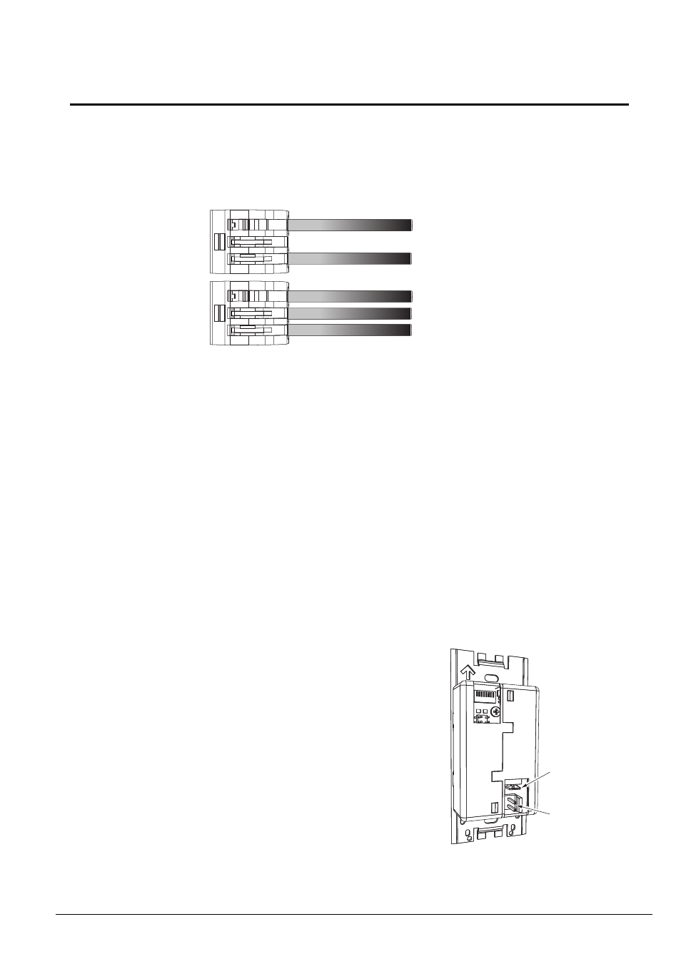
Topology of a
single station
installation
Topology of
multiple stations
installed in series
Installed control wire
Pigtail wire
Installed control wire
Installed wire to next station
Pigtail wire
Ground
spade
LinkPower
connector