Attach new power harness – ETC Sensor+ CE Rack (ESR+) CEM+ to CEM3 Retrofit User Manual
Page 9
2
The Retrofit
7
Step 5:
Disconnect the DMXA wires from slots 1,2 and 3 of the J2 connector.
Step 6:
Connect the DMXA wires to an 8-pin connector. DMXA wires connect to the
following terminals: Gray wire - 1, Black - 2, Red - 3.
Step 7:
Disconnect the DMXB wires from slots 9 and 10 of the J2 connector.
Step 8:
Connect the DMXB wires to another 8-pin connector. DMXB wires connect to the
following terminals: Clear wire - 1, Black - 2, White - 3.
Cap Link Wires (if present)
Step 9:
If your rack has an ETCLink connection, disconnect the link wires from slots #11-
14 of the J2 connector.
Step 10: Secure wires as follows:
a: cut all bare ends from the link wires
b: cap the wire ends with electrical tape
c: coil the wires into a neat bundle and secure with a wire tie
d: Secure the cabling to the side or back of the rack with tie mounts and wire ties
so they do not interfere with normal rack function
Step 11: Finish removing the old backplane metalwork. Discard the old backplane.
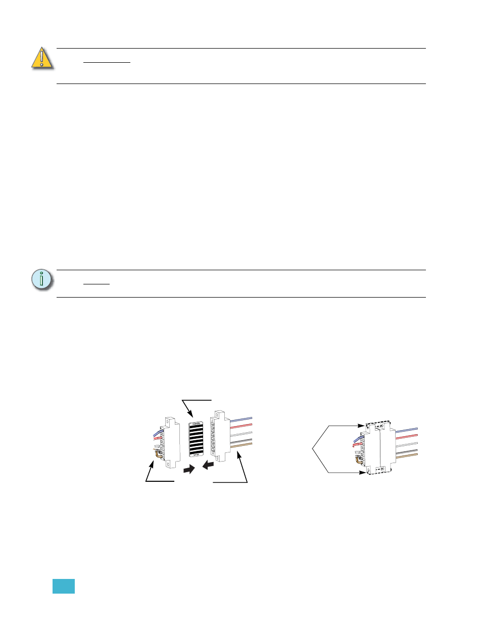
Attach new power harness
Step 1:
Clip the first wire-tie behind the existing J1 power connector to give the harness
more room to move while you work.
Step 2:
Install the power adapter harness to the edge connector (straight thru PCB) and
then to the old power connector (be sure the wire colors match on both sides of
the joined connectors).
.
Step 3:
Secure the power connectors together with the provided 4"-wire-ties. Clip the
wire tie ends for neatness.
C A U T I O N :
If using the IDC connector for CAT5 solid-core wiring, you must start with clean
wire ends (clip the old punched end. Re-punching the old ends could result in an
intermittent or failed connection.
N o t e :
Wire runs for ETCLink are abandoned in the rack and can be used in the future as
DMX wire runs in the event that a DMX line must be replaced for any reason.
Oh, I wish
I were an
Oscar Meyer® w
iener...
Wire-tie the
connectors
together
The PCB is the same on
both sides, top and bottom.
Match the
wire colors