Backplane settings – ETC Sensor+ CE Rack (ESR+) CEM+ to CEM3 Retrofit User Manual
Page 11
2
The Retrofit
9
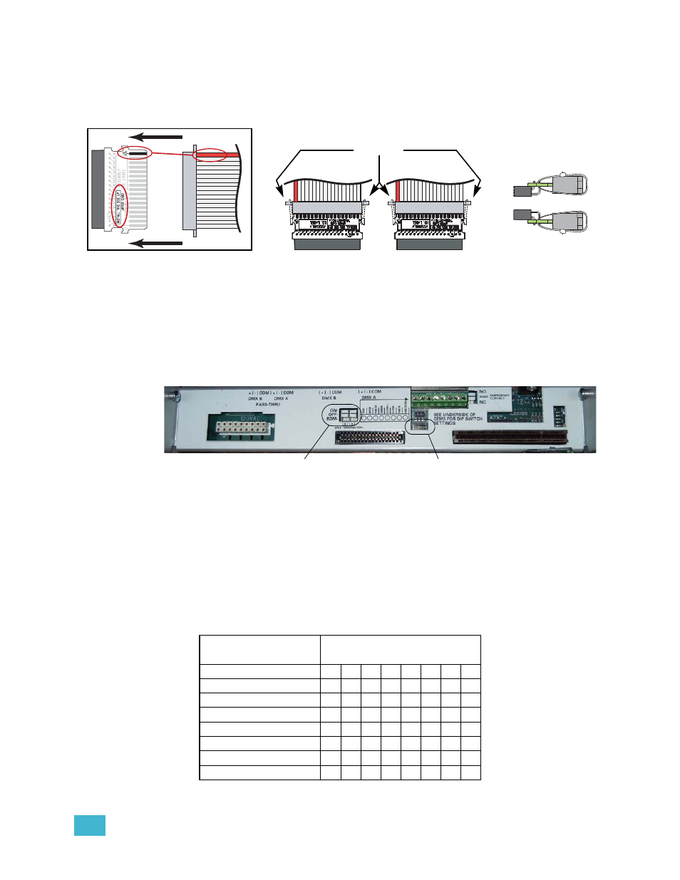
Step 2:
Mate the transition cards with the ribbon cable edge connectors as indicated
below. Secure the ribbon cable connectors to the transition cards with wire ties.
The tie wrap binding needs to be on the top for an Upper board and on the
bottom for a Lower board for clearance. Clip wire tie ends for neatness.
Step 3:
Terminate the ethernet cable with the provided Ethernet Termination Kit (ETC
Part# 4101A2003). Follow the wire preparation and termination instructions
included with the kit. The cable will terminate in a small box (called a “biscuit box”
as referenced in a later step)
Backplane Settings
Upgrade kit backplanes ship from the factory with all DIP switches in the off (down) position.
You will have to set the DIP switches on the new backplane to match your rack. You will
also have to verify the termination switch settings.
a: Set both termination switches to “Off” (middle position) for all racks except the
last rack in your system.
b: Set the termination switches for the last rack in the system to “ON” (top
position).
c: Using a precision screwdriver, set the DIP switches to match your rack type
according to:
• number of modules (6, 12, 24, or 48)
• whether the rack has Advanced Features (AF)
Use the following chart to determine your required DIP switch settings:
“On” position = switch pushed to the top
DIP switch Number
Rack Model
1
2
3
4
5
6
7
8
SR3-6
On On
SR3-6AF
On
On On
SR3-12
On
SR3-12 AF
On
On
SR3-24
On
SR3-24 AF
On
On
SR3-48
SR3-48 AF
On
Match
the red
wire to
pin-1
and be
sure the
proper
side is
up
Wire tie the
connectors
together
Position of the
tie wraps
On top for Upper
On bottom for Lower
Set termination to “Off”
(middle position)
Set DIP switches