The retrofit, Preparation, Remove the old – ETC Sensor+ CE Rack (ESR+) CEM+ to CEM3 Retrofit User Manual
Page 7: N o t e
2
The Retrofit
5
S e c t i o n 2
The Retrofit
Preparation
Step 1:
Use Sensor Configuration Editor and a SLTA if you wish to download and save
the current Sensor configuration out of the racks for later reference. For
information on this process contact ETC Technical Services (see
Step 2:
Turn off main power to the rack(s). Before removing dimmer or control
modules for service, de-energize main feed to dimmer rack and follow
appropriate Lockout/Tagout procedures as described in NFPA Standard
70E. It is important to note that electrical equipment such as dimmer racks
can present an arc flash safety hazard if improperly serviced. This is due
to available large short circuit currents on the feeders of the equipment.
Any work on energized equipment must comply with OSHA Electrical Safe
Working Practices.
Step 3:
Remove the eight dimmer modules above the CEM (if retrofitting an SR48 rack,
remove the eight modules below the CEM as well). Note and document the
modules’ order/positioning in the rack for proper insertion and configuration later.
Step 4:
Use a digital voltmeter and VERIFY that power is off by checking voltages for
all combinations between the phase bars, neutral and ground.
Step 5:
Remove the CEM from the rack.
Remove the Old
Step 1:
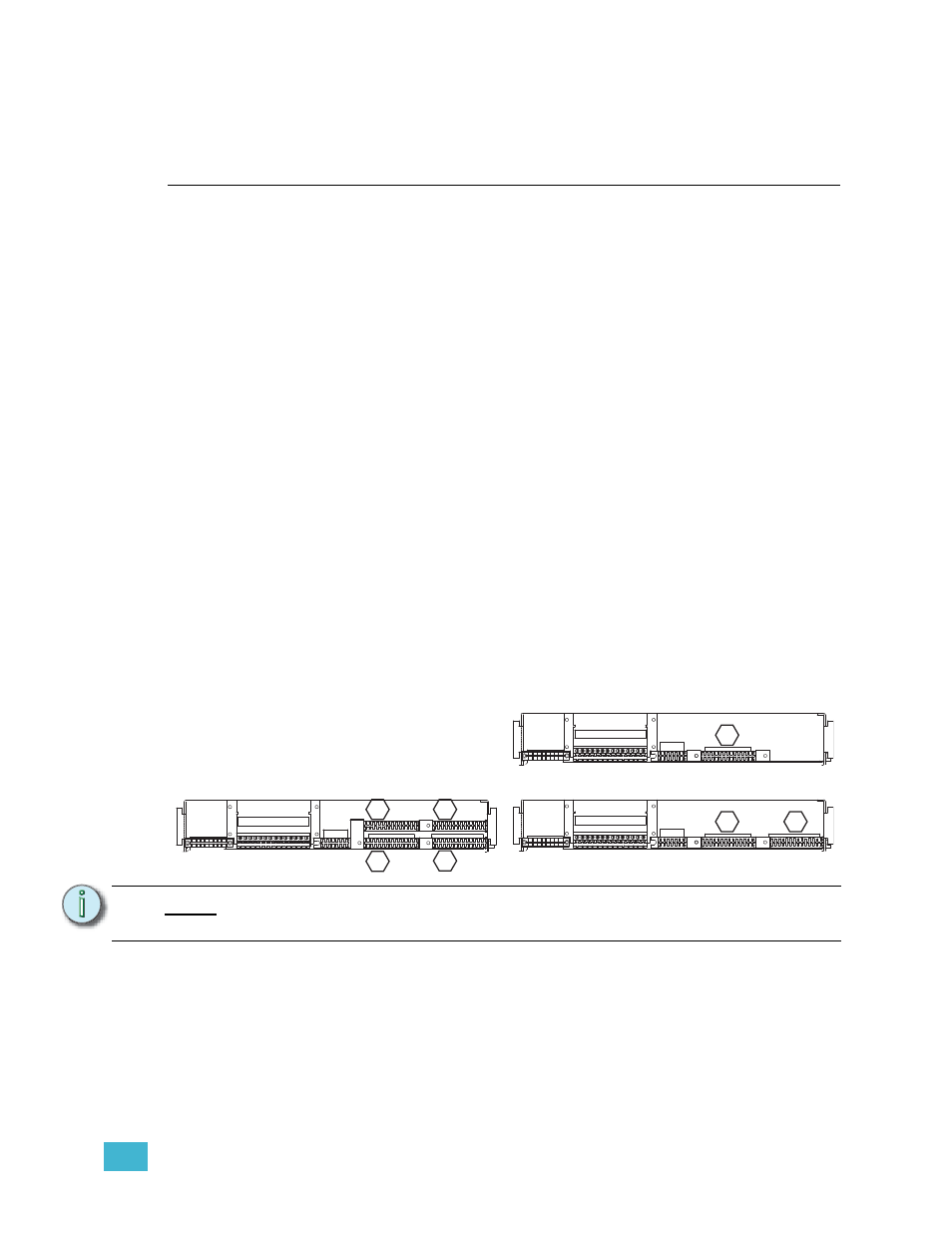
Mark the edge connector of each dimmer output ribbon cable (1, 2, 3 & 4) as
illustrated below in the hexagons. There may be stickers on the ribbon cables
already, however these may refer to cable length and not dimmer outputs. They
should not be used as a reference for these instructions.
Step 2:
Document and/or label each wire that is currently landed on the J2 edge
connector.
Step 3:
Unscrew the dimmer output edge connectors from the backplane metal.
Step 4:
Carefully feed the dimmer output ribbon cables through the backplane.
Step 5:
Examine each ribbon cable for any nicks or cuts that may have resulted from
scraping against the backplane.
Step 6:
Unscrew the power edge connector (J1). Remove it from the backplane by
N o t e :
The order/layout of the dimmer output edge connectors is different on the CEM3
backplane.
1 2 3 4 5 6 7 8 9 10 11 12 13 14
1 2 3 4 5 6 7 8 9 10 11 12 13 14
1 2 3 4 5 6 7 8 9 10 11 12 13 14
CEM SR48 Ribbon Cable Layout
(1-24)
CEM SR6/12 Ribbon Cable Layout
(1-24)
(73-96)
(49-72)
(25-48)
1
1
3
4
2
(25-48)
(1-24)
CEM SR24 Ribbon Cable Layout
1
2
J1
J2
J3
J1
J2
J3
J1
J2
J3