ETC Sensor+ Touring Rack CEM+ to CEM3 Retrofit User Manual
Page 9
2
The Retrofit
7
Step 6:
Unscrew and remove the plastic collars from around the termination buttons on
the new control panel circuit board.
Step 7:
Slide the new circuit board into the control input panel.
Step 8:
Secure the circuit board in place using the 8 screws for the DMX A and B
connectors.
Step 9:
Screw the plastic collars in place around the termination buttons.
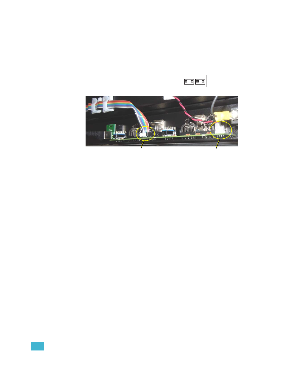
Step 10: Connect the multi-colored DMX ribbon cable to the new circuit board.
Step 11: Connect the beacon connector red and
black twisted pair(s) to either the first or last
pair of the beacon header (shown here).
SP96 racks will use both pairs.
Step 12: If your rack has a neon indicator to the right of the control inputs, this is a “second
fan indicator”. If yours is not labeled, place the label found in the kit (7143A4001)
above the neon indicator.
Use either pair
DMX Cable
Connection
Beacon Wires
Connection