Remove the old, Control input panel replacement – ETC Sensor+ Touring Rack CEM+ to CEM3 Retrofit User Manual
Page 8
6
CEM3 Sensor+ Touring Rack Retrofit Manual
Remove the Old
Step 1:
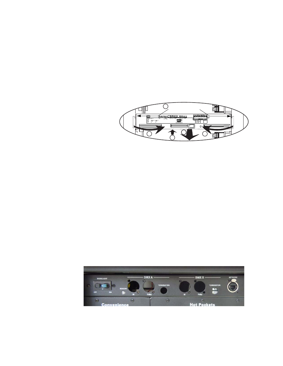
Accessing the rear of the backplane through the rack side panel, disconnect the
multi-colored DMX ribbon cable and CAT5 cable from the backplane.
Step 2:
Disconnect the power cable from the rear of the CEM+ backplane.
Step 3:
Disconnect the dimmer output ribbon cables from the backplane. As you remove
the ribbon cables, mark them with a permanent marker to indicate the proper
order for reattachment (Dimmers 1-24, 25-48, and so on). There may be stickers
on the ribbon cables already, however these may refer to cable length and not
dimmer outputs. They should not be used as a reference to these instructions.
Step 4:
Unscrew the backplane metal from the rack. (One screw in each side upper-
corner - two screws total.) Discard these screws. Replacement screws with
thread locker are provided (ETC Part# HW377) and will be used later.
Step 5:
Push the backplane towards the back of the rack to free the backplane side tabs.
Step 6:
Bend the sides in towards the center (out of the sides of the rack).
Step 7:
Slide the backplane metal forward in order to allow easier working space while
removing the data terminations
Step 8:
Pull one side forward to angle the backplane then remove the backplane
metalwork from the rack. Discard the old backplane.
Control Input Panel Replacement
Step 1:
Disconnect the DMX ribbon cable from the rear of the input panel circuit board.
Step 2:
Disconnect the beacon connector red and black twisted pair(s) from the beacon
header (one pair - either left or right - for small racks; two pairs in 96-channel
racks).
Step 3:
Unscrew and remove the plastic collars from around the DMX termination
buttons on the control input panel.
Step 4:
Remove the screws that hold the DMX A and B connectors in place (8 screws
total - save these screws as you will need them in a later step). You do not need
to remove the screws for the network connector.
Step 5:
Slide the old control panel circuit board out of the panel and remove it from the
rack.
6
8
8
9
7
Remove the
backplane screws