Cem3 power harness termination – ETC Sensor+ Touring Rack CEM+ to CEM3 Retrofit User Manual
Page 12
10
CEM3 Sensor+ Touring Rack Retrofit Manual
Step 9:
Plug the control input ribbon cable into the blue header on the backplane. The
connector is keyed - the ribbon cable will travel upwards from the backplane.
Step 10: Plug the 2' Ethernet cable into the RJ45 connector on the rear of the backplane.
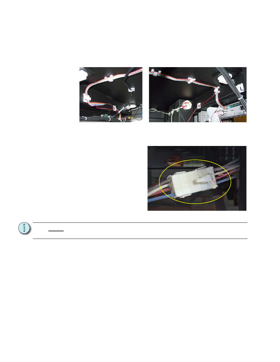
Step 11: Dress the control data ribbon cable, the beacon cable and the Ethernet cable
through the cable clips neatly across the top of the rack. The cables should be
supported every 6” to 8” from the control input panel to the backplane. Use the
provided ribbon cable mounts (ETC Part# HW726) as needed.
CEM3 Power Harness Termination
Step 1:
Connect the old power
connector to the new power
harness. The connectors
are keyed - the power
connectors only fit one way.
Step 2:
Run the green ground wire
from the power harness
adapter down to an open
terminal in a grounding strip
for any outlet panel (such
as VEAM, twistlock, or
other outlet type - VEAM is
preferred). Grounding
terminal screws can be
loosened or tightened with a flat-blade or square drive screwdriver.
N o t e :
Depending on the interior of your touring rack, you may wish to secure the power
harness wires out of the way using tie wraps and sticky-back mounts if necessary.
Cable routing on the input panel side
Cable routing on the CEM3 side